1. Common Compliance Sourcing Mistake: Over-specification Causes Unnecessary Cost Waste
When purchasing EMC shielded rapid temperature change test chambers and building compliance qualification systems, most enterprises fall into a typical pitfall — over-specifying equipment and adopting high-end industrial or military standards for general product testing.
The electronics industry features four clear compliance tiers: Consumer, Industrial, Automotive, and Military. Each tier has distinct testing standards, parameter thresholds, and environmental requirements. A one-size-fits-all high-end configuration brings no compliance benefits, but significantly increases capital expenditure, laboratory operation costs, and daily power consumption.
With over 20 years of testing industry experience, Lab Companion provides a scientific tiered compliance matching system. We help companies select fully compliant yet cost-effective equipment, ensuring 100% standard compliance while minimizing overall testing costs.
2. Tiered Compliance Boundaries: Differentiated Testing Requirements
Each product tier corresponds to independent international standards and technical indicators. Clear tier differentiation is the foundation of precise and low-cost compliance:
Consumer Grade (smart home devices, consumer electronic modules)Compliance Standards: IEC 60068, CE, FCCKey Parameters: temperature range -20℃~85℃, temperature change rate 5–10℃/min, shielding efficiency ≥60dBSuitable for basic environmental adaptability and conventional EMC verification for civilian products.
Industrial Grade (industrial sensors, control modules)Compliance Standards: Industrial IEC standardsKey Parameters: temperature range -40℃~100℃, temperature change rate 10–15℃/min, shielding efficiency ≥70dBFocuses on long-term operational stability and durability under industrial working conditions.
Automotive Grade (vehicle electronic components)Compliance Standards: AEC-Q series, ISO 16751Key Parameters: temperature range -40℃~125℃, loaded temperature change rate ≥20℃/min, full-band shielding efficiency ≥80dBDesigned for harsh and dynamic vehicle operating and electromagnetic environments.
Military Grade (defense and high-reliability components)Compliance Standards: GJB, MIL-STD seriesKey Parameters: temperature range -70℃~180℃, rapid temperature change rate ≥25℃/min, high-level shielding efficiency ≥90dBMeets extreme temperature impact and strong electromagnetic interference test requirements for mission-critical equipment.
3. Double Cost Loss Caused by Non-tiered Sourcing
Blind equipment selection leads to two major cost risks that widely exist in the industry.
Many enterprises purchase automotive or military-grade high-spec chambers for consumer and industrial product testing. This over-specification increases procurement costs by 40%–60%. Meanwhile, high-end chambers consume more power and require more complex maintenance, resulting in continuously high long-term operation costs and severe resource idleness.
In contrast, some companies choose underrated equipment for high-grade product certification. Substandard technical parameters lead to invalid test data and certification failures. The subsequent repurchase and retesting generate secondary costs, including time loss, certification delays, and repeated labor costs.
The core value of Lab Companion’s tiered compliance solution is to eliminate double waste: over-investment for low-tier products and non-compliance risks for high-tier products.
4. Lab Companion Tiered & Modular EMC Chamber Solutions
Lab Companion launches professional tiered EMC shielded rapid temperature change chamber series, precisely matching the four product compliance levels to achieve accurate performance matching and optimal cost control.
Consumer Grade SolutionOptimized and simplified redundant high-end functions while retaining all required parameters for CE and FCC certification. It reduces procurement and operation costs by 35% and fully meets daily compliance testing demands for consumer electronics.
Industrial Grade SolutionEnhanced loaded operation stability and long-running durability. It adapts to continuous industrial condition testing and provides higher cost performance than universal standard chambers.
Automotive Grade SolutionEquipped with standard 25℃/min loaded temperature change, 80dB full-band shielding, and real-time dynamic parameter monitoring. It fully meets the rigid indicator requirements of mainstream automotive certification standards.
Military Grade SolutionAdopts military-grade cavity structure and high-efficiency refrigeration systems, supporting ultra-wide temperature range, ultra-fast temperature cycling, and high electromagnetic shielding performance to comply with strict MIL-STD and GJB standards.
5. Full Lifecycle Cost Optimization & Global Technical Support
To support long-term cost control and product iteration, Lab Companion adopts a modular upgrade design for all chambers. Clients can upgrade temperature change rate, shielding level, data acquisition system, and other functions on demand without replacing the entire machine, effectively avoiding repeated high investment for equipment iteration.
In consideration of global service characteristics, no on-site door-to-door maintenance is provided for overseas regions. Instead, we provide professional online guidance and remote technical support throughout the product lifecycle. Customized tiered maintenance guidance helps customers avoid excessive maintenance costs and further optimize laboratory operating expenses.
Conclusion
Smart compliance relies on accurate matching rather than excessive configuration. Lab Companion’s tiered compliance system, modular equipment design, and full-lifecycle cost optimization services effectively solve the industry’s over-specification and non-compliance problems. We help global enterprises achieve standard-compliant, cost-effective, and efficient laboratory operation, supporting steady business growth with reliable and economical testing solutions.
1. Industrial Chain Compliance Becomes a Mandatory Entry Threshold
The global electronics manufacturing industry has formed a rigorous top-down compliance transmission mechanism. Leading downstream manufacturers, automotive enterprises, aerospace & defense institutions, and communication giants have officially includedEMC & thermal cycling combined testing capability as a core assessment indicator for supplier admission, annual qualification audits, and supply chain grading.
Today, supply chain compliance is no longer an optional advantage, but a prerequisite for entering high-end supply chains and maintaining cooperative qualifications. Downstream clients enforce strict standards for product reliability and electromagnetic compatibility, which are fully transmitted to upstream suppliers of chips, modules, components, and auxiliary materials. Suppliers without independent composite testing capabilities will be eliminated from high-end supply chain systems.
Based on global industrial compliance standards, Lab Companion provides professional EMC-shielded rapid thermal cycling test chamber solutions that fully match international audit requirements, helping global suppliers break compliance barriers and stabilize their supply chain qualifications.
2. Core Compliance Audit Requirements for Four Key Industries
Compliance audits vary across application scenarios, with increasingly strict and industry-specific standards for different downstream sectors:
Automotive Industry: Leading automotive and new energy enterprises require Tier 1 and Tier 2 suppliers to deliver full AEC-Q compliant testing. Independent thermal cycling and EMC synchronous testing is mandatory. All test data must be fully traceable, and equipment must hold valid third-party calibration certification to qualify for supplier listings.
5G Telecommunications: Top communication equipment providers require component suppliers for optical modules and AAU units to support high-frequency EMC shielding tests and rapid thermal cycling durability tests, ensuring product adaptability for harsh outdoor base station operating environments.
Aerospace & Defense: This sector adopts the most stringent audit standards. All testing equipment, operational procedures, and data management systems must fully comply with GJB 150/151 standards with complete auditability and traceability.
Consumer Electronics: Global premium brands enforce IEC and EN standard compliance testing to ensure full market access for worldwide product distribution.
3. Major Compliance Challenges Faced by Midstream & Upstream Suppliers
Most small and medium-sized upstream suppliers are currently facing prominent compliance bottlenecks. Most enterprises only own standalone thermal cycling equipment or basic EMC testers, which cannot support composite stress testing and fail to meet downstream audit criteria.
Many suppliers rely entirely on third-party testing laboratories, which brings three major drawbacks: high long-term testing costs, lengthy test cycles, and inconsistent test environments compared to actual production conditions. This hidden risk often leads to quality issues after mass delivery.
In addition, outsourcing testing cannot help enterprises accumulate independent, standardized test data, resulting in unstable annual audit performance and potential supply chain elimination. Industry statistics show that over 30% of medium and small electronic component suppliers have been removed from high-end supply chains in the past two years due to insufficient in-house compliance testing capabilities.
4. Lab Companion’s Tailored Compliance Solutions for Global Supply Chains
Lab Companion has thoroughly analyzed the supplier audit specifications of global leading enterprises and optimized our EMC-shielded rapid thermal cycling chambers to fully align with international compliance requirements.
Our equipment fully meets the audit standards of the automotive, telecommunications, aerospace & defense, and consumer electronics industries. Test procedures, precision parameters, EMC shielding performance, and data management systems are perfectly matched with global downstream audit rules.
Each unit is delivered with a complete set of official documents, including third-party calibration certificates, performance verification reports, and compliance qualification files, which can be directly applied for supplier registration and annual audits, greatly simplifying customers’ compliance preparation work.
5. Independent In-House Testing Upgrades Supply Chain Competitiveness
With Lab Companion professional test equipment, customers can build independent, controllable, and traceable in-house testing capabilities. Enterprises can complete R&D verification, incoming inspection, mass production reliability testing, and batch compliance rechecks without relying on external third-party laboratories, effectively shortening testing cycles and reducing operational costs.
Continuous in-house testing helps enterprises build exclusive product reliability databases, support iterative product optimization, and improve supply chain evaluation scores. This enables manufacturers to shift from passive compliance to active quality improvement, forming sustainable differentiated competitiveness in global supply chains. To date, hundreds of global upstream suppliers have upgraded their compliance capabilities with Lab Companion equipment and successfully entered top-tier international supply chain systems.
6. Global Service Model (No On-Site Support)
To adapt to global business deployment, Lab Companion adopts a standardized overseas service system. We do not provide on-site door-to-door maintenance or after-sales services in overseas regions. Instead, we deliver full-process professional online technical guidance, including equipment installation guidance, operation training, parameter debugging, daily maintenance guidance, and remote troubleshooting support. Our efficient online service system ensures stable and continuous equipment operation for global customers.
Conclusion
As global supply chain compliance supervision becomes increasingly refined and standardized, independent in-house testing capability has become the core foundation for suppliers to stabilize high-end international supply chain partnerships. With internationally compliant, audit-friendly, and fully traceable testing equipment, Lab Companion helps global customers eliminate compliance barriers, consolidate supply chain qualifications, enhance industrial competitiveness, and promotes standardized and high-quality development of the global electronics manufacturing industry.
1. The Hidden Challenge: Combining Thermal Cycling with EMC Testing
In electronic product validation, thermal environmental testing and EMC compliance testing are traditionally performed separately. Manufacturers first complete temperature cycling reliability tests, then move the Device Under Test (DUT) to an anechoic chamber for emission and immunity verification.
However, critical device failures often only occur under combined thermal and electromagnetic stress — such as low temperature with specific RF fields or high temperature with transient interference. These intermittent issues cannot be replicated through separate tests, leading to undetected design flaws.
Many engineers attempt to run simultaneous thermal and EMC tests by placing the DUT inside a standard temperature chamber while connecting external antennas and measurement probes. In practice, this approach causes severe noise floor elevation of more than 10 dB, resulting in unreliable and invalid measurement data.
The root cause lies in the inherent electromagnetic leakage and self-noise defects of conventional thermal chambers.
2. Three Major EMC Leakage Weaknesses of Standard Temperature Chambers
Standard temperature chambers are designed purely for thermal insulation and moisture resistance, with no consideration for electromagnetic shielding. Their structural gaps, penetration openings, and internal electronics create unavoidable interference paths.
2.1 Door Seals & Viewing Windows: Uncontrolled RF Leakage Points
Standard door rubber gaskets are designed for thermal sealing only and provide zero attenuation for high-frequency electromagnetic waves. The hollow glass viewing windows contain no conductive shielding layer, acting as an open RF aperture on the chamber enclosure.
Within the 300MHz~3GHz common EMC frequency range, structural gaps match the wavelength scale, allowing external interference to couple into the chamber and internal DUT emissions to leak outward. This completely compromises test accuracy.
2.2 Tubing & Cable Penetrations: Natural Waveguide Paths
Refrigeration copper tubes, sensor wires, heater power cables, and fan motor wires must penetrate the chamber wall. Standard chambers only apply basic thermal sealing without RF shielding treatment.
These metallic pipelines and unfiltered penetrations act as waveguides, transmitting internal device noise outward and channeling external electromagnetic interference into the test volume.
2.3 Built-in Electrical Noise: The Chamber Itself Becomes an Interference Source
To achieve fast temperature ramping, standard chambers adopt SSR chopping heating, variable-frequency compressor drives, and DC fan speed regulation. These high-speed switching circuits generate significant broadband harmonics and RF noise.
The built-in noise radiates through air, chassis, and power lines. During EMC testing, receivers and probes capture chamber self-noise instead of the DUT’s true electromagnetic performance, making test results invalid.
3. Core Shielding Principles for EMC-Capable Thermal Chambers
A genuine EMC-rated temperature chamber is not simply a metal-shell chamber. It requires a systematic shielding design based on three non-negotiable principles: shielding continuity, full penetration filtering, and low-impedance grounding.
Principle
Definition
Implementation in Lab Companion Chambers
Shielding Continuity
No excessive gaps or apertures on the shielding enclosure to prevent RF leakage
Finger-stock door shielding, metal mesh shielded window, waveguide cutoff tube structure
Full Filtering
All wires and signals crossing the shield boundary must be filtered
EMI power filters, filtered signal connectors, isolated fiber penetration
Low-Impedance Grounding
Stable low-resistance return path for stray current and static discharge
Independent inner chamber grounding, multi-point earth bonding, dedicated grounding bus
4. Lab Companion Engineered EMC Shielding Solutions
Lab Companion EMC temperature chambers are engineered to eliminate RF leakage and self-noise fundamentally, delivering stable, repeatable thermo-EMC coupled test performance for global R&D and compliance labs.
4.1 Integrated Shielded Inner Chamber with Ultra-Low Leakage Structure
Lab Companion adopts a fully welded container-style shielding inner chamber, structurally isolated from the outer frame to ensure complete shielding integrity.
• Door Shielding: Precision beryllium copper or stainless steel finger stocks ensure uniform contact resistance and long-term shielding stability after repeated cycling.
• Shielded View Window: Multi-layer metal mesh embedded glass provides over 50dB shielding effectiveness from 0.5GHz to 3.0GHz (typical value), balancing visibility and RF isolation.
• Waveguide Cutoff Penetration: All refrigeration pipes and drainage tubes pass through cutoff tubes with a length of at least 3 times the tube diameter, blocking RF wave propagation along metallic pipelines.
4.2 Customizable Filtered Interface Panel System
Lab Companion’s modular interface panel solves the critical pain point of unfiltered cable penetration. Customers can configure dedicated, pre-filtered ports to fix test wiring topology permanently, ensuring excellent test repeatability.
Penetration Type
Lab Companion Standard Solution
Optional Upgrade
AC Power (220V/380V)
Two-stage EMI filter, ≥60dB differential & common-mode attenuation @150kHz~30MHz
High-grade customized filters
DC Power (12V/24V/48V)
Filtered connectors + feedthrough capacitors for common-mode suppression
Surge protection module integration
Low-Speed Signals (CAN/LIN/RS485)
Filtered D-sub connectors with independent π-filter per line
Fiber optical isolation penetration
RF Signals (Antenna/Probe)
N/SMA feedthrough connectors with waveguide cutoff structure
7/16 DIN / BNC customized interfaces
Fiber Optic
Standard FC/SC/LC non-conductive feedthrough flanges
Armored fiber protection tube
4.3 Low-Noise Electrical Design to Eliminate Self-Interference
To avoid chamber self-noise overriding DUT weak signals, Lab Companion optimizes every electrical component:
• Zero-crossing SSR heating control reduces high-speed switching harmonics;
• Compressor VFD equipped with input EMI filters and shielded grounding cables;
• Low-noise brushless DC fans with ferrite core noise suppression;
• Independent shielded housing for control units and separated power/signal wiring layout.
The final empty-chamber noise floor is extremely low across the full temperature range, ensuring only genuine DUT electromagnetic characteristics are measured.
5. Real-World Application Case: Automotive Electronics EMC Problem Solving
A global Tier 1 automotive supplier needed to verify the radiated emission performance of a new domain controller under -40℃~+85℃ temperature cycling.
Initially, the customer used a standard thermal chamber with temporary wiring penetrations. The setup caused 8dB noise elevation at low temperatures and external RF signal coupling at high temperatures, leading to false failure judgments.
After upgrading to a Lab Companion 408L EMC shielded temperature chamber with customized filtered interfaces (4-channel power filtering, 2-channel CAN filtering, 2 SMA RF ports), the test environment was fully optimized:
• Full-temperature-range noise floor fluctuation controlled within 2dB;
• A unique low-temperature 125kHz narrow-band emission spike was accurately captured — a failure completely invisible in room-temperature standalone EMC tests;
• The R&D team optimized DC-DC layout and filtering design, achieving formal vehicle-level EMC certification.
6. Selection Guide & Global Service Support
An EMC thermal chamber is not a cosmetic upgrade — it is a professional test system built to eliminate RF leakage and self-noise. Lab Companion’s systematic shielding, filtered interface customization, and low-noise electrical design fully meet thermo-EMC coupled test requirements for automotive, industrial, renewable energy, and high-precision electronics worldwide.
For accurate solution evaluation before purchasing, please prepare the following key parameters:
• DUT dimension, weight and power consumption
• Required temperature range and ramp rate
• EMC test frequency band and limit standards
• Detailed list of power, signal and RF penetration ports
Global Online Technical SupportLab Companion provides full-range online technical guidance, remote commissioning, and after-sales technical support for global users. To adapt to overseas deployment scenarios, we do not offer on-site door-to-door service. Professional engineers deliver fast, accurate remote support for equipment setup, parameter configuration, testing debugging, and daily technical consultation, ensuring stable and efficient operation of your test system.
In 2026, Avoid Price and Brand-biased Test Chamber Selection
As semiconductor manufacturing scales down to 3nm and below, reliability testing standards for AI chips, automotive-grade semiconductors and high-speed optical modules have become increasingly stringent. Thermal cycling chambers, rapid temperature change chambers and thermal shock chambers now play a critical role across the entire product lifecycle, from wafer design verification and package testing to mass production quality screening. The accuracy and stability of these chambers directly determine the validity of test data and product time-to-market.
However, global procurement teams still rely heavily on brand reputation or manufacturer datasheet nominal parameters when making purchasing decisions. This outdated selection method leads to frequent post-purchase risks: off-spec temperature performance under loaded conditions, poor compatibility with customized test workflows and delayed technical support. Instead of superficial indicators, buyers should evaluate suppliers from four practical dimensions: real-world loaded performance, full-range product portfolio, customized integration capability, and global remote after-sales support.
With over 20 years of experience in environmental reliability testing equipment, Lab Companion has served more than 10,000 industrial clients worldwide. Drawing on our flagship TC-series rapid temperature change chambers and TS3-series three-zone thermal shock chambers, this article outlines a standardized, buyer-centric evaluation framework to guide high-tech manufacturing and semiconductor companies in data-driven equipment selection.
Dimension 1: Core Technical Performance — Loaded Operating Conditions Determine Test Credibility
Datasheet-only performance data often deviates drastically from actual on-site operation. Five interconnected technical indicators must be verified under loaded conditions to comply with JEDEC, SEMI and ISO international testing standards.
1. Full Temperature Range Coverage
Semiconductor components require differentiated temperature envelopes based on application scenarios. Consumer-grade ICs typically require a range of -40℃ to +125℃, while AEC-Q100 automotive chips mandate -70℃ to +150℃. Aerospace and military-grade bare chips demand extended extreme ranges up to -80℃ to +200℃ to pass third-party qualification audits.
All standard Lab Companion rapid temperature change chambers support a stable temperature range of -70℃ to +150℃ for continuous 24/7 operation. Custom deep-cooled models extend coverage to -80℃ to +200℃. Our portfolio covers compact 180L units and mainstream capacities including 150L, 225L, 408L and 800L, with no temperature drift or forced defrost downtime under extreme thermal cycling.
2. Load-regulated Temperature Change Rate
Temperature ramp rate is the primary performance metric for rapid thermal cycling tests. A widespread industry pitfall is inflated no-load ramp parameters: many suppliers advertise 20℃/min ramps that drop by over 50% once heat-generating test samples are loaded.
Lab Companion TC-series chambers offer five adjustable linear ramp rates: 5℃/min, 10℃/min, 15℃/min, 20℃/min and 25℃/min, with one-click switching between linear and non-linear ramp modes. All contractual parameters explicitly specify loaded ramp performance rather than no-load figures. In a deployment with a global AI chip developer, our loaded 20℃/min ramp capability cut full-range thermal cycling test duration from 4 days to 1 day. The chambers maintain ±0.1℃ temperature resolution and ±0.3℃ transient temperature fluctuation across all operating scenarios.
3. Temperature Uniformity and Stability
For high-precision components such as coherent optical modules and sub-3nm chips, minor temperature inconsistencies inside the chamber cause inconsistent batch test results and failed CNAS data traceability audits. The international standard IEC 60068 requires temperature uniformity within ±1.0℃, while advanced semiconductor testing demands stricter tolerances.
Powered by the in-house Q8 intelligent control system with dual-PID regulation and AI fuzzy disturbance compensation, Lab Companion chambers deliver sustained performance of ±0.3℃ temperature fluctuation and ±0.5℃ internal temperature uniformity across the full -70℃ to +150℃ range. This meets testing requirements for quantum chips and millimeter-wave semiconductor components with ultra-tight tolerance limits.
4. Dynamic Thermal Load Adaptation
Unlike passive industrial test samples, operational semiconductor chips generate variable real-time heat output, shifting from low standby power to high peak power within seconds. Traditional single-PID controllers fail to offset dynamic internal heat loads, triggering temperature overshoot and permanent damage to bare dies.
The Q8 control system integrates high-frequency thermal load sensors that monitor sample heat dissipation 10 times per second. It automatically adjusts refrigeration airflow and cooling capacity without manual intervention. Auxiliary environmental disturbance compensation offsets fluctuations in ambient room temperature and grid voltage, ensuring 99.5% repeatability for batch production test datasets.
5. Dew Point Control and Condensation Prevention
Condensation during rapid temperature transitions causes BGA pad short circuits, gold finger oxidation and irreversible component failure. All Lab Companion chambers adopt seamless 304 mirror stainless steel interiors for dust-free operation. Optional dry nitrogen purging lowers internal dew points below -40℃, eliminating condensation and oxidation risks during high-acceleration thermal cycling. The sealed internal structure also complies with ISO 14644 cleanroom deployment rules.
Dimension 2: Scalable Product Portfolio — R&D to Mass Production Compatibility
Inconsistent testing equipment across R&D, pilot and mass production stages breaks data traceability, one of the top pain points for global semiconductor labs. Disparate control algorithms from different vendors lead to incomparable test results and extended qualification cycles.
Lab Companion provides a fully scalable equipment lineup covering bench-top 34L compact chambers to 16m³ walk-in environmental rooms. The TS3 three-zone thermal shock chamber adopts physically isolated hot and cold zones to prevent cross-contamination of internal airflow, optimized for fragile optical and semiconductor components. Specialized variants including battery explosion-proof chambers complete coverage for electronic components, circuit assemblies and full-size automotive modules. All devices share unified control logic, data export protocols and calibration standards for cross-stage data consistency.
Dimension 3: Customized Hardware and Software Integration Capability
Over 80% of semiconductor reliability projects require non-standard modifications rather than off-the-shelf equipment. Common custom requirements include SEMI-compliant cleanroom interface adaptation, automatic docking with ATE testers and probe stations, reserved automated material handling ports, and extended extreme temperature envelopes.
Lab Companion delivers fully integrated custom solutions with an average lead time of 60 days, far shorter than the global industry average of 90–120 days. For a global power semiconductor manufacturer, we redesigned internal airflow and refrigeration loops within a 100L chamber to achieve -60℃ to +160℃ loaded thermal cycling at 15℃/min, with temperature uniformity locked at ±0.3℃. All standard units are pre-fitted with RJ45 and RS485 communication ports for native LIMS and MES system integration, eliminating third-party adapter compatibility risks.
Dimension 4: Global Remote Lifecycle Technical Support
On-site on-demand after-sales service is not standard practice for cross-border industrial equipment suppliers due to regional regulatory, logistics and labor restrictions. Lab Companion provides a 100% remote-first global support system tailored for overseas clients, with no mandatory on-site maintenance included in standard warranties.
Our global remote support team operates across 6 time zones with 24/7 ticket response. Technicians conduct real-time system diagnosis, parameter recalibration, firmware upgrades and fault troubleshooting via encrypted cloud remote access. For replaceable consumables and core spare parts, we maintain regional spare part warehouses in North America, Europe and Southeast Asia, with standard international shipping delivery within 3–5 working days.
Post-delivery remote services include virtual commissioning, recorded operator training, annual remote calibration guidance and lifelong firmware updates. All support documents, operation manuals and compliance certificates are provided in English, German, Japanese and simplified Chinese to align with regional industrial regulatory requirements.
Final Selection Guidelines for Global Buyers
For 2026 cross-border environmental test chamber procurement, prioritize evaluation criteria in the following order, ignoring superficial brand influence and low-price tenders:
1. Loaded performance first: Verify ramp rate and temperature uniformity under actual sample load, not only datasheet no-load data
2. Cross-stage compatibility: Select suppliers with unified control systems for R&D and mass production equipment
3. Integration customization: Confirm native digital interface compatibility rather than post-purchase retrofitting
4. Remote support reliability: Audit time zone coverage and spare part logistics instead of on-site service commitments
Lab Companion’s unified global product standards, AI-powered temperature control and timezone-adapted remote support match the compliance and operational demands of automotive, semiconductor and aerospace clients worldwide.
Dual Threats to 5G Base Stations: Internal Heat Accumulation & Extreme Ambient Temperature Fluctuations
Global large-scale 5G deployment and vertical industry integration are accelerating. Shenzhen hosts 442 5G upstream and downstream enterprises, the largest cluster worldwide, with local 5G applications covering 91 categories of national economic sectors. Despite robust industrial growth, thermal reliability defects have become a top risk for outdoor 5G infrastructure long-term operation.
Compared with 4G counterparts, 5G macro base stations adopt massive MIMO antenna arrays and GaN high-power RF amplifiers, driving a sharp surge in power consumption. Field data shows RF front-end power density of 5G devices is over 3 times higher than 4G, with local heat flux exceeding 300W/cm² and instantaneous component surface temperatures hitting 120°C — far beyond the 85°C safe operating threshold for telecom hardware. Beyond internal heat generation, outdoor deployment exposes base stations to harsh cross-climate conditions: units operate 24/7 across -40°C to +85°C, enduring cyclic thermal stress from diurnal temperature swings and seasonal climate shifts that degrade circuit boards, solder joints and waterproof seals over time.
Combined thermal overload and rapid temperature cycling trigger cascading failures. Minor issues include RF gain attenuation, signal phase distortion and unstable data throughput. Severe faults cover chip thermal throttling, solder joint fatigue cracking and partial antenna failure, ultimately causing base station outages. As a result, standardized environmental simulation testing equipment that replicates real-world outdoor thermal conditions has become mandatory for 5G R&D, validation and mass production quality control.
Founded in 2005, Lab Companion (Guangdong Hongzhan Technology) specializes in R&D and manufacturing of environmental reliability testing systems. Its TC-series rapid thermal change chambers are widely deployed in 5G RF modules, high-speed optical transceivers and semiconductor packaging worldwide. This paper analyzes how Lab Companion addresses 5G thermal reliability challenges from industrial pain points, core product capabilities, global application cases and overseas remote service frameworks.
1. Industry Pain Points: Outdated Testing Solutions Fail Updated Telecom Standards
5G overheating risks stem from fundamental architectural upgrades. Massive MIMO expands antenna channels from 8 (4G) to 64/128 for 5G, while mainstream GaN power amplifiers push AAU power consumption to 1000W-1500W. Legacy passive heat sinks and basic air cooling designed for 4G lack sufficient thermal margin, making them unable to verify structural durability under rapid thermal cycling.
International and regional telecom standards have tightened reliability benchmarks. Per YD/T 3627-2023 and YD/T 4110-2022 (globally recognized reference standards for 5G hardware), outdoor AAUs require long-term thermal-humidity endurance testing from -40°C to +70°C with temperature fluctuation accuracy within ±0.5°C. Mandatory rapid thermal shock tests are also required to validate BGA solder joints, RF connectors and sealing performance under minute-level temperature transitions.
Conventional temperature cycling chambers feature fixed ramp rates and poor temperature uniformity, failing to meet updated compliance requirements. The global telecom supply chain demands scalable, high-precision rapid thermal change systems with flexible configuration capabilities.
2. Core Advantages of Lab Companion TC-Series Rapid Thermal Change Chambers
Customized for passive and active telecom component validation, all TC-series units hold CE certification for global shipment. The portfolio covers 9 standard chamber volumes ranging from 34L to 1500L, supporting testing for discrete RF chips, compact optical transceivers and integrated small-cell base stations to cover full-scale component and finished-product validation.
2.1 Modular Ramp Rate Configuration to Avoid Over-Engineering
Different 5G components show divergent thermal sensitivity. The TC series supports both linear and non-linear temperature ramp rates from 5°C/min to 25°C/min across five adjustable tiers. Non-linear ramp modes prioritize internal cavity temperature uniformity, ideal for batch screening of passive antenna arrays. Linear ramp modes comply strictly with JEDEC solid-state component specifications, eliminating hidden component damage caused by abrupt temperature shifts for RF baseband chips and high-speed optical modules.
Thanks to modular refrigeration architecture, users can upgrade ramp performance via add-on refrigeration modules without full equipment replacement when testing standards update. For extreme low-temperature scenarios including 5G millimeter-wave component validation, optional liquid nitrogen auxiliary cooling kits are available to break mechanical refrigeration speed limits for automotive and military-grade telecom compliance.
2.2 Ultra-Wide Temperature Range for Global Climate Replication
5G base stations are deployed across Arctic cold zones, arid inland regions, humid coastal areas and high-altitude plateaus, with cross-regional temperature differentials exceeding 100°C. The TC series delivers a core temperature range of -70°C to +150°C, providing ample testing redundancy beyond the -40°C to +85°C standard requirement for mainstream 5G hardware. The matched TH-series combined temperature-humidity chambers offer 20%RH to 98%RH humidity regulation, replicating high-temperature high-humidity conditions for 85°C/85%RH long-term aging tests required for coastal outdoor telecom infrastructure.
2.3 Dual Cascade Refrigeration: High Precision with Low Energy Consumption
Unlike single-stage refrigeration used by generic competitors, TC chambers adopt dual cascade refrigeration loops with environmentally compliant refrigerants: zero-ODP R23 for low-temperature circuits and low-loss R404A for high-temperature circuits. Paired with Copeland and Danfoss hermetic dual-stage compressors, the system cuts energy consumption by 18% under identical thermal ramp conditions. Nickel-chromium alloy heating tubes ensure uniform heat distribution, while dual PID collaborative control eliminates temperature overshoot and drift.
The multilingual touchscreen interface simplifies parameter configuration, with built-in power-off recovery, automatic calibration and scheduled startup functions to support unattended 24/7 lab operation, a core requirement for overseas automated testing labs.
2.4 Cloud-Based Intelligent Monitoring for Traceable Test Data
Powered by Lab Companion proprietary fuzzy PID algorithms, the chambers maintain temperature fluctuation within ±0.5°C and spatial deviation within ±2°C, fully meeting international telecom calibration standards. Local storage retains 5+ years of temperature curves and fault logs with exportable Excel/PDF reports for ISO 17025 and CNAS audit compliance. Built-in Ethernet connectivity enables cloud remote monitoring: global clients can remotely start/stop tests, view real-time thermal data and receive fault alerts via desktop or mobile terminals. The system features 32 automatic fault diagnosis protocols with multilingual troubleshooting prompts to accelerate on-site staff resolution without manual manuals.
3. Global Field Application Cases Across the 5G Supply Chain
3.1 RF Front-End Module R&D Validation
RF front-end modules directly determine 5G signal stability. A global leading massive MIMO antenna supplier adopted Lab Companion TC-100L chambers to conduct -55°C to +125°C rapid thermal cycling and 1000-hour 85°C/85%RH aging tests per YD/T 4110-2022. Uniform cavity thermal conditions identified hidden failures including adhesive delamination and gold-plated connector oxidation before mass production. Post-test verification confirmed frequency error within ±0.04ppm and output power fluctuation below ±2.2dB, meeting global operator access specifications.
3.2 Integrated Small-Cell Base Station Mass Screening
Outdoor small cells face severe diurnal thermal swings in urban and roadside deployments. A Southeast Asian telecom integrator deployed TC-340L chambers for 500+ cycles of -40°C to +70°C thermal shock testing to simulate 5 years of outdoor operating stress. Repeatable high-precision temperature control eliminated early failures of motherboard solder joints and power capacitors, reducing field failure rates from 1.2% to 0.27% for shipped units.
3.3 800G/1.6T High-Speed Optical Transceiver Testing
Laser chips in next-gen optical transceivers show extreme thermal sensitivity, with minor temperature shifts triggering code errors and optical power attenuation. Lab Companion compact TC models are widely used by transceiver manufacturers across Europe and Southeast Asia. Standard 10°C/min linear thermal cycling from -40°C to +85°C verifies extinction ratio, receiver sensitivity and bit error rate stability for cabinet-mounted transceivers operating without active cooling.
4. Overseas Service Framework: Remote-Only Support for Global Clients
Lab Companion does not provide on-site door-to-door maintenance for overseas clients, complying with cross-border logistics and local labor regulatory restrictions. We deliver full-lifecycle remote technical support covering all overseas regions, with standardized global service rules:
• Warranty Coverage: 1-year global comprehensive warranty for labor and standard components; 3-year extended warranty for core components including compressors and main control boards, with lifelong free remote technical consultation.
• In-Warranty Support: Unlimited multilingual remote video guidance for installation, calibration, routine maintenance and fault diagnosis; free digital firmware updates and electronic operation manuals. No on-site dispatch is included in overseas warranty packages.
• Post-Warranty Support: Transparent component pricing with no hidden fees. All spare parts are shipped from overseas bonded warehouses with standardized international logistics lead times.
• Remote Response SLA: 2-hour response window for urgent technical inquiries via email, video call and dedicated customer portal; detailed remote troubleshooting reports delivered within 12 working hours.
5. Future Outlook: 5G-A and 6G-Oriented Testing Innovation
Global telecom networks are transitioning to 5G-A commercial deployment, with 6G millimeter-wave, integrated sensing and communication (ISAC) technology under active R&D. Millimeter-wave antennas will see heat flux exceeding 500W/cm² and wider thermal tolerance ranges, driving demand for combined thermal-vibration environmental testing.
Lab Companion will prioritize two core upgrades for global clients: low-carbon refrigeration optimization to align with EU carbon border adjustment regulations, and combined thermal-shock-vibration testing systems for 6G ISAC hardware. We will continue to deliver high-precision, scalable and low-energy environmental simulation solutions, supporting global telecom manufacturers to improve long-term device reliability across cross-climate deployments.
The rapid iteration of high-compute AI chips has driven stricter requirements for environmental stress testing. With higher integration density and soaring power consumption, modern AI chips face extreme thermal stress during R&D and mass production. Traditional temperature cycling tests can no longer effectively expose marginal failures and potential reliability risks.
As a highly efficient accelerated reliability verification method, HALT (Highly Accelerated Life Testing) applies extreme temperature cycling stress far beyond standard operating conditions. It rapidly exposes functional limits and latent defects in the early development stage, shortening validation cycles and improving product robustness.
Lab Companion high-speed thermal cycling chambers deliver ultra-fast temperature ramping, intelligent load adaptation, and precision thermal control. Designed for high-power AI chip and server system testing, our solutions provide standardized, repeatable HALT verification for global semiconductor and AI enterprises.
1. Unique HALT Testing Challenges for High-Power AI Chips
Modern AI hardware features ultra-high power density. A single high-end GPU consumes hundreds of watts under full load, while a complete AI server rack can exceed 10kW peak power. Such dynamic and high heat loads bring three critical challenges to HALT testing:
1.1 Temperature Overshoot Under Ultra-Fast Ramp Rates
Qualified HALT testing requires a minimum temperature change rate of 25℃/min. Conventional testing equipment adopts traditional PID control, which struggles with rapid temperature transitions, causing severe overshoot and undershoot. Uncontrolled temperature spikes exceed specification limits and may damage expensive engineering samples, leading to high R&D losses and invalid test data.
1.2 Poor Stability Against Dynamic Internal Heat Loads
During powered testing, AI chips and GPU modules continuously generate dynamic heat, equivalent to an unstable internal heat source inside the chamber. Traditional systems cannot compensate for real-time heat fluctuations, resulting in inconsistent ramp rates and poor test repeatability. This makes it impossible to accurately define the true operational limits of AI chips.
1.3 Condensation Risks During Extreme Thermal Cycling
Rapid temperature transitions between extreme low and high temperatures easily cause surface condensation on chip packaging and precision components. Uncontrolled moisture leads to short circuits, metal corrosion, and electrochemical migration, causing irreversible damage to high-reliability AI chips used in data centers and 5G infrastructure.
2. Core Technical Advantages of Lab Companion HALT Thermal Cycling Chambers
With decades of expertise in environmental test equipment R&D and manufacturing, Lab Companion high-speed thermal cycling chambers are fully optimized for industrial-grade HALT scenarios. The standard model supports a 25℃/min linear ramp rate, while the LN2-assisted version achieves a maximum cooling rate of 30℃/min, fully complying with international HALT industry standards.
2.1 Ultra-Wide Temperature Range & Industry-Leading Ramp Speed
The standard temperature range covers -70℃ to +150℃, with customized extended models reaching -80℃ to +200℃. Multiple ramp rates from 5℃/min to 25℃/min are available, supporting both linear and non-linear cycling modes. Equipped with an optional liquid nitrogen auxiliary cooling system, the cooling rate reaches 30℃/min, accurately simulating extreme working conditions such as sudden power-off cooling and instant full-load heating.
In the classic HALT cycle (-40℃ ↔ 85℃), the 30℃/min ultra-fast cooling mode reduces single cooling cycle time to 5 minutes, boosting test efficiency by over 400% compared with conventional equipment. Hundreds of accelerated thermal cycles can be completed in a short time to efficiently expose latent defects and greatly shorten chip R&D validation cycles.
2.2 Q8 Intelligent Control System with AI Load Adaptive Algorithm
Lab Companion self-developed Q8 control system integrates AI fuzzy algorithms and dual-PID adjustment technology. It predicts temperature variation trends in advance and dynamically adjusts heating and cooling power. Across the full temperature range, the temperature fluctuation is ≤±0.3℃ and uniformity ≤±0.5℃, delivering consistent and stable stress output.
The core intelligent load recognition technology is optimized for high-power AI hardware testing. The system automatically identifies dynamic heat load characteristics of fully loaded GPUs, AI chips, and server modules, and matches optimal control parameters in real time. It effectively suppresses temperature overshoot under 25℃/min high-speed cycling, ensuring zero damage to precision samples. Built-in anti-interference compensation offsets ambient temperature and voltage fluctuations, achieving 99.5% test data repeatability.
2.3 Dual-Stage Cascade Refrigeration + LN2 Auxiliary Cooling System
The chamber adopts a dual-stage cascade refrigeration system with independent R404A high-temperature and R23 low-temperature circulation loops, ensuring stable and continuous operation within the standard temperature range. For ultra-low-temperature and extreme acceleration test requirements, the optional LN2 direct-injection auxiliary cooling system works with mechanical refrigeration to significantly improve low-temperature cooling efficiency, stably supporting 30℃/min ultra-fast cycling and meeting strict HALT limit stress assessment standards.
2.4 Split Structure & Professional Anti-Condensation Design
Adopting a split structure that separates the refrigeration unit from the test chamber, the equipment effectively reduces ambient heat accumulation and operating noise, supporting 72-hour unattended continuous operation for long-term HALT aging tests. Equipped with a dual-stage dehumidification and automatic dry air purging system, it replaces humid air during low-to-high temperature transitions, eliminating condensation risks on chip surfaces and precision electronic components.
3. Typical Application Scenarios for Global AI Chip R&D
3.1 Limit Stress Verification for High-Compute GPU Modules
For commercial high-power GPU modules used in AI servers, HALT testing is essential to define operational boundaries and failure thresholds. Customers adopt Lab Companion LN2-assisted high-speed thermal cycling chambers to complete -60℃ to +100℃ non-linear rapid cycling tests at a rate ≥25℃/min.
Under full-load high-heat conditions, the temperature overshoot is strictly controlled within ±0.5℃ with excellent uniformity. The Q8 system continuously records multi-point temperature data during 72-hour unattended operation, dynamically adapting to load changes. The exported complete test reports provide reliable data support for product reliability optimization and specification definition.
3.2 System-Level Thermal-Humidity Coupling Testing for AI Servers
For full 42U rack-mounted AI server system-level verification, Lab Companion large-volume walk-in thermal cycling chambers (2000L) support overall machine testing. The equipment achieves ±0.5℃ temperature uniformity and ±1.5%RH humidity accuracy, covering 20%–95%RH wide humidity range and -50℃ to +70℃ temperature cycling conditions.
The automatic anti-condensation system protects internal precision devices during temperature transitions. The system supports seamless docking with customer MES and data management platforms, realizing automatic data uploading and full lifecycle traceability, providing credible reliability certification for global market delivery.
3.3 Rapid Screening Verification for Low-Power Edge AI Chips
For low-power edge AI chips applied in smartphones and wearable devices, R&D teams need fast HALT screening to identify design weaknesses before mass production. Lab Companion TC series compact high-speed chambers provide 20℃/min non-linear cycling and a -70℃ to +150℃ wide temperature range.
Even for low-power samples below 5W, the intelligent load recognition system can accurately identify subtle heat changes and stabilize temperature transition curves. It efficiently completes limit temperature approximation and electrical performance verification, helping customers eliminate mass production risks and accelerate product iteration.
4. Q8 Intelligent System: Digital HALT Test Management
Tailored for high-standard global HALT testing workflows, the Q8 intelligent control system integrates full-process digital management functions:
• Flexible Program Editing: Supports up to 1000-segment custom programming, adaptable to complex test curves such as step stress, cyclic impact, and limit approximation. Built-in standard HALT templates simplify programming operations.
• Complete Data Traceability: Multi-channel real-time data acquisition, automatic trend curve generation and test report export, with 600-day local data storage to meet international quality audit standards.
• Remote IoT Management: Standard IoT module supports real-time equipment status monitoring, parameter adjustment and progress viewing via PC and mobile terminals, realizing unattended and efficient remote test management.
• AI Predictive Maintenance: 24/7 real-time monitoring of core components such as compressors and heaters. The AI health assessment algorithm predicts potential failures in advance, reducing unplanned downtime and ensuring continuous test progress.
5. Global Standardized Remote Technical Support System
To adapt to overseas customer service models, Lab Companion provides full-lifecycle online technical support for global users, without on-site door-to-door services, ensuring professional and efficient support for overseas R&D and production projects:
• 24/7 Online Technical Response: Professional international technical team provides fast remote docking, answering equipment operation, parameter debugging and fault consultation in real time.
• Remote Calibration & System Inspection: Support remote data verification, parameter calibration and system health detection to ensure long-term test accuracy compliant with HALT standards. All products comply with ISO9001, ISO14001 and CE international certifications.
• Standardized Operation Training & Document Support: Provide complete English SOP operation manuals, video training resources, and support customized HALT test process guidance for customer products.
• Remote Debugging & Technical Escort: For batch equipment users, provide exclusive remote commissioning, operational guidance and long-term technical escort services to ensure stable equipment operation.
6. Core Product Strength Summary
• Extreme Thermal Cycling Capability: 5–25℃/min optional standard ramp rates, up to 30℃/min with LN2 assistance, fully compliant with international HALT accelerated test specifications.
• High-Precision Constant Temperature Control: AI + dual-PID algorithm ensures ≤±0.3℃ temperature fluctuation and ≤±0.5℃ uniformity, realizing zero overshoot and safe limit stress application.
• Intelligent Dynamic Load Adaptation: Automatically identifies diverse heat loads of chips, modules and servers, with test data repeatability up to 99.5%.
• Ultra-Wide Temperature Coverage: Standard -70℃ to +150℃, customized -80℃ to +200℃, covering all extreme thermal environment simulation scenarios.
• Diversified Volume Configuration: 36L–10000L full-size coverage, supporting customized walk-in models, adapting from single chips to full server rack testing.
• Intelligent Digital Management: Remote monitoring, automatic data backup and one-click report export, matching digital R&D management systems of global semiconductor enterprises.
• Global Standard After-Sales System: Full-process online remote technical support, compliant with overseas user service habits, stable and efficient.
Conclusion
From single edge AI chips to high-compute server systems, Lab Companion high-speed thermal cycling chambers deliver ultra-fast temperature cycling, high-precision intelligent control and adaptive load testing capabilities. We provide standardized, reliable and intelligent HALT reliability verification solutions for global AI and semiconductor enterprises. With mature industrial technology and global standardized service systems, Lab Companion helps customers continuously optimize chip reliability, accelerate product iteration, and empower the high-quality development of the global AI computing industry.
1. Challenges of Automotive Chip Testing & Importance of AEC-Q100 Standard
Driven by the rapid growth of the global new energy vehicle industry, automotive-grade chips are deployed in increasingly complex application scenarios. Widely adopted in battery management systems, ADAS domain controllers, in-vehicle infotainment, and vehicle stability modules, automotive chips must maintain stable performance throughout the vehicle’s service life under extreme temperature fluctuations, continuous mechanical vibration, and long-term humid environments.
Among all reliability stresses, thermal shock is one of the leading causes of chip packaging failure, wire bond fracture, and solder joint cracking. To unify reliability requirements for automotive electronic components, the Automotive Electronics Council (AEC) established the AEC-Q100 standard, which has become a globally recognized benchmark for automotive component qualification.
The standard clearly defines temperature transition rates, cycle counts, dwell time, and failure judgment criteria for thermal shock testing. Strict and precise thermal shock testing is a mandatory prerequisite for chips to obtain vehicle-grade certification.
With rich expertise in environmental test equipment, Lab Companion has developed professional thermal shock test chambers to address the stringent reliability testing demands of automotive chips. Fully compliant with AEC-Q100 specifications, our equipment delivers high-precision temperature control, fast thermal response, and long-term operational stability, serving new energy vehicle manufacturers and tier-1 suppliers across global markets.
2. Core Technical Advantages of Lab Companion Thermal Shock Test Chambers
2.1 Dual / Triple Zone Structure for Ultra-Fast Thermal Transition
AEC-Q100 requires test samples to switch rapidly between high and low temperature extremes. Lab Companion thermal shock chambers adopt a pneumatic dual or triple independent zone structure. Equipped with insulated partitions and a high-speed sample transfer mechanism, the system completes sample zone conversion within 5–10 seconds.
Unlike traditional single-chamber temperature cycling systems that suffer from air mixing and temperature cross-contamination, our isolated zone design delivers pure and effective thermal shock stress. The equipment stably supports classic AEC-Q100 test conditions, including -40℃~125℃ and -55℃~150℃. Even under full load conditions, the chamber maintains standard-compliant temperature conversion speed, accurately simulating real-world vehicle conditions such as extreme heat soaking, cold start, and rapid temperature fluctuation.
2.2 High Precision Temperature Control & Low Long-Term Drift
Temperature deviation during testing may lead to invalid results, causing misjudgment of chip qualification. Lab Companion integrates adaptive PID algorithms and high-precision platinum resistance sensors, controlling temperature fluctuation within ±0.5℃ in both high and low temperature zones.
By optimizing the matching of refrigeration and heating power, the equipment ensures temperature drift ≤2% after 500+ hours of continuous operation. This outstanding stability guarantees consistent and repeatable test results for batch chip qualification.
2.3 Intelligent Anti-Condensation & Auto Defrost Control
When samples transfer from high-temperature zones to low-temperature zones, instantaneous surface condensation may occur, which is prohibited by AEC-Q100 to avoid circuit short-circuit and corrosion failures. Lab Companion equips each chamber with a dry air purging system and intelligent defrost logic.
The targeted airflow design keeps sample surface temperature above the dew point without liquid condensation. Meanwhile, the system automatically adjusts defrost cycles based on operating status, ensuring uninterrupted test loops and fully compliant test environments.
2.4 Complete Data Traceability & Remote Monitoring
To meet standardized batch testing requirements, Lab Companion thermal shock chambers come with built-in Ethernet communication and professional PC software. The system records real-time data of each thermal shock cycle, including temperature curves, sample status, dwell duration, and equipment operating parameters.
All data is encrypted and tamper-proof, fully complying with the data traceability requirements of ISO 16753 and AEC-Q100. Users can remotely monitor equipment status via local network and receive instant alerts via email and SMS in case of abnormal conditions, greatly improving test efficiency and controllability.
3. Full Compliance with AEC-Q100 Thermal Shock Test Specifications
AEC-Q100 temperature cycling (TC) and early-life thermal stress tests are core items for automotive chip certification. Lab Companion test chambers fully cover Grade 0 to Grade 4 automotive chip test requirements through comprehensive technical capabilities.
Full Temperature Coverage: The chamber supports a wide temperature range of -70℃~200℃, completely covering standard requirements of -50℃~125℃ and extreme -65℃~150℃ test conditions for all automotive chip grades.
Precise Dwell Time Control: Independent high/low temperature dwell time setting with an accuracy of ±30 seconds, fully meeting the standard requirement of a minimum 10-minute dwell time at extreme temperatures.
High-Cycle Durability: The equipment supports more than 2000 consecutive thermal shock cycles, far exceeding the standard 500–1000 cycle requirements, ensuring long-term stable batch testing.
Real-Time Sample Temperature Monitoring: Optional wireless temperature sensors attach directly to chip surfaces to monitor actual sample temperature, ensuring the temperature difference between air and sample remains within the 10℃ tolerance specified by AEC-Q100.
All equipment can be calibrated by third-party authoritative institutions to provide CNAS-certified calibration reports, supporting customers’ IATF 16949 audits and official automotive certification processes.
4. Global Application in New Energy Vehicle Reliability Testing
Lab Companion thermal shock test chambers are widely adopted by new energy vehicle manufacturers, semiconductor design companies, and tier-1 automotive component suppliers. Our equipment serves core automotive industry clusters with standardized and customized thermal shock testing solutions for motor control chips, BMS chips, and ADAS chips.
4.1 ECU Controller Chip Qualification (1000-Cycle Thermal Shock Verification)
A tier-1 automotive electronic supplier needed to verify IGBT driver chips for vehicle motor controllers, requiring AEC-Q100 Grade 1 certification (-40℃~125℃, 500 cycles). With Lab Companion dual-zone thermal shock chambers, the customer completed full-process qualification, including preconditioning, continuous thermal shock testing, and final electrical parameter verification. The equipment operated stably for 7 consecutive days without over-limit alarms, helping the chip pass automotive certification and achieve mass production approval.
4.2 Extreme BMS Chip Testing (-55℃~150℃ High-Grade Verification)
A new energy battery manufacturer required its BMS front-end chips to meet AEC-Q100 Grade 0 standards (-55℃~150℃, 1000 cycles). Lab Companion provided a customized triple-zone thermal shock chamber with an expanded sample basket, supporting 200 chips per test batch and significantly shortening the certification cycle. Equipped with an enhanced low-humidity protection function, the equipment effectively avoids condensation risks during extreme high-low temperature switching, ensuring valid and reliable test results.
4.3 Global Online Technical Support & Stable After-Sales Service
To adapt to global customer demands, Lab Companion provides worldwide online technical support. Our professional engineering team offers remote equipment commissioning, operational guidance, parameter calibration, and fault diagnosis services. Without on-site maintenance dependence, customers can obtain fast and professional technical responses globally, ensuring continuous and stable test operation.
5. Key Criteria for Selecting Automotive-Grade Thermal Shock Test Chambers
When purchasing AEC-Q100 compliant test equipment, manufacturers should evaluate comprehensive performance rather than focusing merely on initial procurement cost. Lab Companion recommends five core evaluation dimensions:
1. Standard Compliance: Verify whether the equipment can provide complete test data curves that meet AEC-Q100 and JESD22 standards, along with official third-party calibration certificates for audit support.
2. Full-Load Test Performance: Ensure the chamber can recover to set temperature within 5 minutes under full sample load conditions, avoiding inconsistent performance between no-load and loaded tests.
3. Long-Term Operational Reliability: Adopt high-quality core configurations including imported fully hermetic compressors, durable heating elements, and dynamically balanced fans to support long-term high-frequency cyclic testing.
4. Secure & Traceable Test Data: Support tamper-proof data storage and timestamp-embedded PDF/CSV data export to meet automotive-grade data archiving and traceability requirements.
5. Professional Global Technical Support: Equipped with a professional remote engineering team to provide 24/7 online guidance, equipment debugging, training, and technical troubleshooting for global users.
6. Conclusion & Future Outlook
Automotive chip reliability is the fundamental guarantee for safe and stable operation of new energy vehicles. High-standard thermal shock testing is an indispensable step in automotive-grade certification and mass production quality control.
As a professional global provider of environmental test solutions, Lab Companion delivers fully AEC-Q100 compliant, high-precision, and high-stability thermal shock test chambers. With in-depth standard mastery, mature core technology, and reliable global online support, we help global new energy vehicle and semiconductor customers accelerate certification progress and improve product reliability.
Looking ahead, with the widespread adoption of 800V high-voltage platforms and SiC automotive chips, future thermal shock test conditions will become more extreme, featuring wider temperature ranges and higher cycle counts. Lab Companion is actively researching next-generation ultra-fast temperature transition technology and plans to launch a new generation of high-end thermal shock chambers by 2027, continuing to empower the high-quality development of the global new energy vehicle industry.
Booming Shanghai AI Computing Industry Brings New Thermal Testing Challenges
As a core hub for AI chip R&D and computing infrastructure in China, Shanghai’s Zhangjiang and Caohejing industrial clusters have witnessed explosive growth in domestic high-performance AI chips. Since 2026, local leading enterprises have achieved remarkable market breakthroughs: Biren Technology has successfully listed on the Hong Kong Stock Exchange with an oversubscription ratio exceeding 2,300 times and a peak market value of HK$100 billion. Muxi Technology debuted on the STAR Market with a nearly 700% first-day surge, pushing its market value up to RMB 350 billion. OriginAI has completed IPO counseling and is accelerating its listing process. Three of China’s top four domestic GPU developers are rooted in Shanghai, forming a leading industrial cluster for high-end AI chip innovation.
The regional industrial advantages continue to expand. Hygon AI’s regional headquarters has settled in Pudong Zhangjiang, while Yuntiantianxin advances the industrialization of high-power inference chips. As Shanghai’s AI computing hardware rapidly upgrades in performance, extreme heat generation has become a critical bottleneck for reliability validation.
High-computing AI chips produce massive instantaneous heat during parallel computing tasks. Without rigorous thermal cycling verification in R&D and mass production phases, devices are prone to frequency reduction, performance degradation and premature hardware failure. Traditional thermal test equipment can no longer adapt to the high-power, large-scale, high-precision testing requirements of modern AI chips and server systems. To address these industry pain points, Lab Companion has developed high-acceleration fast temperature change chambers, delivering standardized, high-reliability environmental test solutions for global AI computing hardware manufacturers.
Three Core Testing Pain Points of High-Power AI Chips
Compared with traditional consumer electronics chips, AI GPUs, server motherboards and full rack servers feature ultra-high power consumption, severe thermal accumulation and oversized test specimens, bringing three major technical challenges to temperature cycling tests.
1. Severe Thermal Accumulation Causes Unstable Test Data
The thermal design power (TDP) of a single mainstream AI GPU reaches hundreds of watts. A multi-GPU server delivers a peak power consumption of over 10kW, while high-density racks exceed 50kW to 100kW — 3 to 5 times higher than traditional servers. During temperature cycling tests, the self-heating of DUTs (devices under test) distorts the internal temperature field of the chamber, causing significant deviations between the set temperature and the actual ambient temperature around specimens. This results in poor repeatability and authenticity of test data, failing to meet international reliability standards.
2. Traditional PID Control Leads to Temperature Overshoot & Specimen Damage
Qualified fast temperature change tests require smooth heating and cooling processes without overshoot or delay. However, conventional PID control struggles with high-heat-load AI devices. It provides insufficient power during heating and generates severe temperature overshoot when approaching the target value due to sudden heat release from high-power chips. Excessive temperature deviation not only violates IEC and JESD test specifications but also damages expensive engineering samples, raising R&D costs significantly.
3. Limited Chamber Volume Fails Full-System-Level Testing
Modern AI reliability testing has evolved from single IC testing to system-level verification of GPU motherboards, multi-GPU modules and complete server racks. Standard temperature change chambers cannot accommodate large-size DUTs. Forced placement blocks internal airflow, destroys temperature field uniformity, and fails to support full-system reliability validation for AI servers.
Lab Companion Core Technologies for High-Heat-Load AI Testing
Lab Companion TC/TH/ESS/CW series fast temperature change chambers are tailor-made for high-power, large-size AI computing hardware. With exclusive optimized control algorithms and structural design, the equipment supports full-scenario testing from single chips and modules to complete server racks.
1. Wide Temperature Rate Coverage with Linear & Non-Linear Modes
Lab Companion chambers feature a temperature range of-70℃ to +150℃, with temperature fluctuation ≤±0.5℃ and temperature deviation ≤±2℃. It supports multiple temperature change rates from 5℃/min to 25℃/min, with optional linear and nonlinear operation modes. Liquid nitrogen auxiliary cooling is available for ultra-fast cooling up to 30℃/min.
Linear temperature variation ensures constant and smooth temperature gradients, perfectly matching standardized compliance tests that require strict rate consistency. Nonlinear mode simulates real-world operating conditions such as equipment startup/shutdown and load fluctuation, reproducing actual thermal shock environments for more credible test results.
2. Patented Adaptive Thermal Load Control Algorithm Eliminates Overshoot
To solve the overshoot problem caused by high self-heating of AI chips, Lab Companion adopts a patented cold-end adaptive control system, upgrading traditional PID logic. The system collects real-time data from multiple temperature sensors inside the chamber and on specimen surfaces, dynamically identifies the real-time power load of DUTs, and intelligently adjusts compressor output and heater compensation to offset self-heat interference.
Even under high-speed temperature cycling above 15℃/min, the equipment achieves smooth temperature transition with strictly controlled overshoot range. It ensures the thermal stress applied to specimens fully complies with international standards, guaranteeing test accuracy and protecting high-value test samples.
3. Large Walk-In Chambers for Full-Rack System-Level Testing
Lab Companion walk-in fast temperature change chambers cover a volume range from 1m³ to 10m³, with customizable oversized dimensions to accommodate standard 42U AI server racks and complete system equipment. The series supports ultra-high thermal load testing, bearing 1,000kg aluminum ingots plus 50kW continuous heat load, with expandable load capacity for customized demands.
Equipped with a multi-point three-dimensional air supply system, high-power centrifugal fans and adjustable deflectors, the chamber forms a full-domain forced convection circulation. Under full-load conditions, the temperature uniformity ≤±1.5℃ and fluctuation ≤±0.5℃, fully meeting GJB and IEC requirements for large-scale specimen reliability testing.
4. Precise Humidity Control Prevents Condensation & Corrosion
Extreme temperature differences during AI chip thermal cycling easily cause surface condensation during temperature recovery, leading to short circuits, circuit corrosion and performance failure. Lab Companion’s integrated boiler humidification system provides accurate humidity control ranging from 20%RH to 98%RH, stably maintaining low humidity conditions of 45%RH at 0℃. It effectively eliminates condensation risks and ensures safe and stable testing of high-precision AI chips.
5. Independent Intelligent Control System with Full Data Traceability
Lab Companion’s self-developed C100 PID control system integrates fuzzy logic algorithms with bilingual (Chinese/English) visual operation interfaces for simple and efficient parameter configuration. The system automatically coordinates refrigeration, heating, dehumidification and humidification subsystems to achieve high-precision full-range temperature and humidity control. It supports intelligent fault self-diagnosis with real-time fault prompts and historical record storage for rapid maintenance.
Equipped with Ethernet and IoT remote monitoring functions, the equipment allows engineers to check operating status and test progress via mobile terminals anytime. All test data, temperature curves and fault records can be exported and backed up, fully complying with IATF 16949, ISO 17025, GJB and IEC data traceability standards.
Typical Application Scenarios for AI Computing Hardware
Scenario 1: GPU Motherboard Temperature Cycle Aging Test
A leading Shanghai AI chip designer conducted reliability verification for high-power GPU motherboards per the JESD22-A104 standard. Test conditions: -55℃ to +125℃, 15℃/min temperature rate, 1,000 thermal cycles. Adopting the Lab Companion TC-1000 fast temperature change chamber, the temperature overshoot was strictly controlled within ±0.5℃ with stable field uniformity. After 1,000 cycles, no cracking, welding failure or structural damage occurred on the GPU motherboard, completing successful reliability validation.
Scenario 2: AI Server Full System Temperature-Humidity Coupling Test
A server manufacturer performed extreme environmental reliability tests on fully loaded AI server racks. The test procedure included 48-hour high-temperature and high-humidity storage at 55℃/95%RH, 24-hour low-temperature storage at -20℃, and temperature recovery cycling. The Lab Companion CW2000 walk-in chamber easily accommodated standard 42U racks and supported external liquid cooling pipeline access for real-time monitoring of core hotspot temperatures. The equipment operated stably for over 300 hours without temperature anomalies or thermal load interference, verifying the long-term stability of server heat dissipation and overall structure.
Scenario 3: ESS Environmental Stress Screening for Multi-GPU Modules
An AI module manufacturer required 100% production-line stress screening to eliminate potential manufacturing defects. Lab Companion ESS series chambers adopt dual/triple-chamber alternating design, realizing seamless switching between testing, pre-heating and pre-cooling to match automated production rhythms. With 24 high-precision temperature acquisition channels, the equipment monitors the real surface temperature of each GPU chip, records temperature deviation data, and generates standardized test reports automatically, meeting strict quality control and traceability requirements for mass production.
Global Online Technical Support System
To serve global enterprise clients efficiently, Lab Companion adopts an online-first technical support system (no on-site door-to-door service for overseas users), providing full-cycle professional technical guarantee:
• Fast Remote Response: Professional technical teams provide remote diagnosis, operational guidance and fault troubleshooting with rapid response worldwide.
• Online Technical Training: Offer remote operational training, standardized SOP documents and customized testing process guidance to help teams master equipment operation quickly.
• Regular Remote Maintenance & Calibration Guidance: Provide periodic remote equipment inspection, calibration guidance and system optimization suggestions to ensure long-term high-precision operation.
• Complete Spare Parts Supply: Support global spare parts delivery and remote component replacement guidance to minimize equipment downtime.
Core Technical Advantages
Lab Companion fast temperature change chambers provide professional and reliable environmental test solutions for global AI chip and server manufacturers, with five core strengths:
• High Thermal Load Adaptability: Patented cold-end adjustment technology eliminates temperature overshoot under high-power load, ensuring precise testing and specimen safety.
• Flexible Temperature Change Rates: Support 5–25℃/min linear/nonlinear adjustable rates, up to 30℃/min with LN2 assistance, adapting to diverse international test standards.
• Full-Coverage Test Space: 1–10m³ large-capacity walk-in chambers support 50kW+ high thermal load for full-server-rack system-level testing.
• Independent & Intelligent System: Self-developed control system with full independent intellectual property rights, supporting remote monitoring and complete data traceability.
• Global Online Support: Professional remote technical team provides 24/7 online guidance, training and after-sales support for overseas clients.
Conclusion
With the continuous upgrading of global AI computing hardware, international standards for chip and server environmental reliability testing are becoming increasingly stringent. Lab Companion focuses on high-precision thermal testing technology, providing full-scenario reliability verification solutions from single chips and modules to complete server racks. By delivering stable, standardized and professional environmental test equipment and global online technical services, Lab Companion empowers global AI hardware enterprises to optimize product reliability and accelerate high-end industrialization development.
High-End Reliability Testing Demands Driven by the Yangtze River Delta Semiconductor Cluster
Wuxi and Suzhou form one of China’s most concentrated and mature semiconductor industrial hubs, boasting a complete industrial chain covering IGBT power module chip design, wafer fabrication, packaging and testing. Wuxi focuses on automotive-grade framed and molded IGBT modules as well as third-generation semiconductor products, while Suzhou specializes in power semiconductor packaging, component R&D and system solution development. The clustered industrial layout lays a solid foundation for high-end power semiconductor manufacturing.
Driven by the booming new energy vehicle, smart grid, industrial frequency conversion and rail transit industries, IGBT power modules are widely deployed in extreme operating conditions. Frequent high-power switching, load fluctuations and sharp temperature changes generate continuous thermal and mechanical stress, posing rigorous challenges to product reliability, thermal stability and service life. In this context, real-world oriented rapid thermal cycling testing has become an indispensable procedure for IGBT module R&D, mass screening and automotive qualification certification.
Tailored to the high-standard testing requirements of the Yangtze River Delta semiconductor cluster, Lab Companion TC/TH series non-linear rapid thermal cycling chambers deliver high-efficiency temperature cycling, high-precision thermal control and full-process data traceability. The series provides standardized, reliable and compliant testing solutions for the entire lifecycle of IGBT power modules, from prototype verification and reliability evaluation to mass production quality control.
1. Core Testing Challenges of IGBT Power Module Thermal Cycling
1.1 Harsh Operating Conditions & Strict Industry Standards
Most IGBT module failures stem from cyclic thermal loads caused by frequent power-on and power-off operations. Rapid junction temperature fluctuations induce thermal stress and mechanical strain, leading to common defects such as material delamination, solder voids and packaging cracking. The IEC 60749-34-1 standard strictly regulates power cycling tests for power semiconductor devices, evaluating the long-term tolerance of IGBTs, MOSFETs and thyristors under repeated thermal and mechanical stress, raising higher requirements for test equipment simulation accuracy.
1.2 Limitations of Traditional Linear Thermal Cycling Equipment
Conventional thermal cycling chambers adopt fixed-rate linear temperature change, which only meets basic testing specifications such as IEC 60068-2-14. This linear mode fails to simulate the irregular, non-uniform thermal shocks caused by real-world load variations, startup-shutdown cycles and working condition switching. In addition, traditional devices lack high-precision full-cycle data recording functions, resulting in insufficient data traceability and failing to meet stringent automotive qualification and mass production audit requirements.
1.3 Unique Advantages of Non-Linear Thermal Cycling Testing
Different from rigid linear temperature variation, Lab Companion non-linear thermal cycling mode allows dynamic rate fluctuation within a compliant range while ensuring the average temperature change rate meets standard requirements. It highly restores the complex thermal impact of IGBT modules under actual operating conditions such as load adjustment and sudden startup. This testing mode effectively exposes latent defects that cannot be detected by linear cycling, including interfacial stress concentration and packaging fatigue failure, greatly improving the authenticity and accuracy of reliability verification.
2. Core Technical Advantages of Lab Companion TC/TH Series
2.1 Ultra-Wide Temperature Range & Multiple Rate Options for Full-Condition Coverage
The chamber covers a wide temperature range of -70℃ to +150℃, fully matching the full operating temperature spectrum of IGBT modules, including -40℃ low-temperature cold start and +125℃ high-temperature full-load operation. It supports multiple standard temperature change rates: 5℃/min, 10℃/min, 15℃/min, 20℃/min and 25℃/min, adaptable to diverse test standards and product specifications. An optional liquid nitrogen auxiliary cooling system further boosts the maximum cooling rate up to 30℃/min to satisfy extreme rapid thermal cycling test demands.
2.2 Dual Linear/Non-Linear Mode Switching for Compliance & Real-World Simulation
All Lab Companion TC/TH series models are equipped with integrated dual-mode switching without additional hardware upgrades, covering R&D verification, certification testing and mass production screening with one device. The linear mode adopts self-developed feedforward compensation algorithm, controlling the rate deviation within ±0.5℃/min and temperature overshoot below 0.8%, fully complying with high-precision automotive-grade standards such as AEC-Q100. The non-linear mode adopts an optimal balance of qualified average rate and energy efficiency, dynamically simulating irregular thermal shocks in real working scenarios while ensuring stable and energy-efficient operation.
2.3 High-Precision Intelligent Temperature Control & Uniform Thermal Field
Equipped with Lab Companion self-developed Q8 intelligent control system, integrated with dual-PID and AI fuzzy algorithms, the equipment real-timely monitors cabin temperature and sample surface temperature, and dynamically adjusts compressor capacity and heater output. It achieves a precise temperature control accuracy of ±0.3℃, temperature fluctuation ≤±0.5℃ and overall temperature deviation ≤±2℃. The temperature difference across the working area is stably controlled within ±1.5℃, ensuring consistent thermal stress loading for every IGBT module and eliminating test errors caused by uneven temperature distribution.
2.4 Full-Process Data Traceability for Automotive Certification Compliance
To meet strict quality audit and certification requirements for power semiconductors, the built-in high-precision data acquisition system records full-cycle temperature, humidity and time parameters in real time with automatic storage and export functions. All test data can generate standardized traceable reports that comply with IATF 16949 and ISO 17025 quality systems, providing complete and credible data support for AEC-Q101 automotive qualification, third-party certification and mass production quality control.
2.5 Expandable Humidity Control for Combined Stress Testing
The TH series supports integrated humidity control function, with a humidity range of 20%~98% RH and precise deviation control: ±3% RH (below 75% RH) and ±5% RH (above 75% RH). It perfectly adapts to high-standard combined stress tests such as H3TRB (High Temperature High Humidity Reverse Bias), covering all mainstream environmental reliability test items for high-end IGBT modules.
3. Typical Application Scenarios for IGBT Module Testing
3.1 AEC-Q101 Temperature Cycle Life Testing for Automotive-Grade IGBT Modules
Automotive-grade IGBT modules require strict temperature cycle life verification per AEC-Q101 standards, which demands high-frequency and wide-range thermal cycling with extremely high requirements for equipment stability and efficiency. Traditional linear testing solutions suffer from long cycle times and poor data consistency, delaying certification progress.
Adopted by multiple automotive semiconductor manufacturers in the Yangtze River Delta, Lab Companion TC series non-linear thermal cycling chambers operate at a rate of 15℃/min under non-linear mode, accurately simulating real thermal stress fluctuations during vehicle load switching. The solution reduces single cycle time by 40% compared with conventional linear equipment. It supports 500+ hours of continuous stable operation with consistent test data, enabling one-pass third-party certification and greatly accelerating product launch cycles.
3.2 ESS Environmental Stress Screening for Mass Production IGBT Modules
Environmental Stress Screening (ESS) is a critical process to eliminate early-stage defects such as solder voids and packaging flaws caused by manufacturing and material inconsistencies. Semiconductor packaging factories adopt Lab Companion non-linear thermal cycling equipment for batch production screening.
The non-linear rate floating control ensures effective stress screening while optimizing energy consumption. The equipment supports uninterrupted operation of more than 200 thermal cycles, with a defrost interval 3 times longer than ordinary devices. It effectively reduces downtime, improves production line screening efficiency and enhances finished product yield, fully adapting to large-scale mass production quality control needs.
3.3 HALT Limit Testing for New IGBT Module R&D
In the new product development stage, HALT (Highly Accelerated Life Testing) is essential to explore the operational and failure limits of IGBT modules and optimize packaging structures and manufacturing processes. Lab Companion equipment supports custom multi-segment non-linear temperature curves, including ramp change, constant temperature holding, stepped cycling and triangular wave impact, with independent parameter configuration for each segment.
By conducting stepped thermal cycling tests within -55℃~+150℃ at an average rate of 20℃/min, manufacturers successfully capture interfacial stress failure points that cannot be triggered by traditional linear testing, providing critical data support for packaging process iteration and structural optimization.
4. Global Online Technical Support System
Lab Companion provides standardized global after-sales technical services, adhering to a remote support-oriented service system to ensure stable and efficient equipment operation for overseas users:
• 24/7 Online Technical Support: Professional engineering teams provide rapid remote response, solving equipment operation, parameter debugging and fault diagnosis problems online in real time.
• Standardized Remote Training: Provide complete SOP operation documents, video tutorials and remote one-on-one training, helping users master equipment operation, calibration and maintenance, and build test systems compliant with AEC-Q101 and GB/T 17574 standards.
• Regular Remote Maintenance & Calibration Guidance: Provide periodic remote equipment inspection, calibration guidance and system optimization suggestions to ensure long-term high-precision and stable operation of the chamber.
• Customized Remote Development & Debugging: Support remote customization of equipment interfaces and cabin layout optimization, realizing linkage adaptation with probe stations, power analyzers and other test equipment to improve overall test integration.
5. Core Product Advantages Summary
• Dual-Mode Compatibility: One-click switching between linear and non-linear modes, balancing standard compliance and real working condition simulation, covering the whole process of R&D verification, certification testing and mass production screening.
• Wide Temperature Range & High-Speed Cycling: -70℃~+150℃ full temperature coverage, 5~25℃/min adjustable standard rate, up to 30℃/min ultra-fast cooling with optional liquid nitrogen cooling system.
• High Precision & Stable Output: ±0.3℃ precise temperature control, uniform thermal field, rate deviation within ±0.5℃/min in linear mode, ensuring accurate and repeatable test data.
• Full-Process Compliant Traceability: Professional data recording system compliant with IATF 16949 and ISO 17025, fully supporting automotive certification and mass production quality traceability.
• Global Professional Remote Service: Standardized online training, remote debugging and long-term technical guidance to ensure efficient and stable equipment operation for global users.
Conclusion
As a core global power semiconductor manufacturing cluster, the Yangtze River Delta is leading the high-end development of domestic IGBT industries. Lab Companion TC/TH series non-linear rapid thermal cycling chambers precisely match the rigorous reliability testing standards of IGBT power modules. With dual-mode thermal cycling technology, high-precision temperature control, full-process data traceability and global standardized remote services, the equipment solves key industry pain points such as inaccurate working condition simulation, insufficient data compliance and difficult overseas after-sales support.
Lab Companion will continue to focus on global power semiconductor testing demands, iterating advanced environmental test equipment and solutions. We empower global customers to improve IGBT product quality and reliability, assisting the power semiconductor industry in achieving high-end and high-quality development worldwide.
Introduction: New Reliability Challenges for MEMS Sensors
As a core cluster of the domestic MEMS sensor industry, Suzhou Nano City hosts more than 550 upstream and downstream enterprises and operates China’s first commercial 6-inch MEMS pilot platform. It has formed a complete industrial chain covering chip design, wafer manufacturing, packaging and testing. Driven by the rapid development of IoT, smart vehicles, aerospace and advanced industrial manufacturing, MEMS sensors are evolving toward higher integration, miniaturization and stricter operating conditions.
Against this backdrop, how to quickly and accurately identify latent defects in MEMS sensor design, material selection and production processes has become a universal industry challenge. To address this demand, Lab Companion has launched the HALT-type high-accelerated thermal cycling chamber. Featuring an ultra-high non-linear temperature change rate of up to 20℃/min, the equipment drastically shortens reliability testing cycles and exposes hidden early failures at the R&D stage, helping global MEMS manufacturers consolidate product quality.
1. High-Accelerated Thermal Cycling Testing: Break Traditional Limits for Extreme Reliability Verification
1.1 What is HALT Testing
HALT (Highly Accelerated Life Test) is an advanced reliability verification method applied in the electronic product R&D phase. Its core principle is maintaining consistent failure mechanisms, intensifying environmental stress, and compressing test duration. By applying extreme thermal cycling and temperature shock stress, HALT rapidly excites potential product weaknesses. Short-term accelerated test data can accurately predict product long-term reliability under standard operating conditions, serving as a critical validation solution before formal product finalization.
1.2 Why MEMS Sensors Require HALT Ultra-Fast Thermal Cycling
Integrated with micro-mechanical structures (cantilevers, thin films, resonant cavities) and precision signal processing circuits, MEMS sensors are far more sensitive to thermal stress and thermal expansion/contraction than conventional electronic components. Standard thermal cycling tests fail to effectively trigger latent failures. The main failure modes of MEMS sensors are summarized as follows:
• Microstructure Fatigue & Fracture: Repeated temperature fluctuations induce fatigue cracks on micro-cantilevers and resonant structures, leading to functional degradation over service time.
• Microstructure Adhesion & Friction Failure: Rapid thermal stress causes irreversible adhesion and stalling of micro-scale structures, undermining sensing accuracy.
• Packaging Thermal Stress Mismatch: Differential thermal expansion coefficients among chips, encapsulation materials and substrates cause stress concentration, resulting in packaging delamination and cracking.
• Interconnection & Solder Joint Failure: Extreme temperature shocks generate microcracks in internal solder joints and circuit interconnections, eventually causing poor contact or open circuits.
Conventional thermal cycling chambers only provide a temperature change rate of 1~3℃/min, requiring several hours for a single complete cycle. Such low stress intensity cannot efficiently expose micro latent defects. In contrast, Lab Companion high-accelerated thermal cycling chambers deliver a temperature change rate of over 10℃/min, enabling extreme high-low temperature switching in a short time. The intensified thermal stress effectively exposes design, material and process flaws, supporting iterative optimization before mass production and eliminating batch failure risks.
2. Core Technical Advantages of Lab Companion High-Accelerated Thermal Cycling Chambers
With years of expertise in environmental reliability testing equipment, Lab Companion independently developed the high-accelerated thermal cycling chamber series. It fully adapts to the full-cycle testing requirements of MEMS sensors from R&D verification to mass screening, solving traditional industry pain points including low efficiency, insufficient precision, contamination risks and incomplete data traceability.
2.1 Customizable Ultra-High Temperature Change Rate, 4X Higher Testing Efficiency
The equipment supports customizable linear and non-linear temperature change rates ranging from 5℃/min to 25℃/min, with top-tier models reaching 25℃/min — far exceeding conventional industry equipment. Taking the mainstream -40℃~125℃ thermal cycle test as an example, traditional devices take 2 hours per cycle, while Lab Companion chambers complete one cycle within 30 minutes. The solution achieves 4 to 5 times more cycles in the same testing period, efficiently stimulating latent failures such as microstructure fatigue and packaging stress defects. Users can freely switch between constant linear temperature change and segmented controllable non-linear acceleration modes according to diverse test standards.
2.2 Wide Temperature Range & High-Precision Control for Batch Test Consistency
Covering a full temperature range of -70℃ to +180℃, the chamber meets all-scenario MEMS testing demands including low-temperature cold start, normal operation, high-temperature storage and extreme temperature resistance. Equipped with a dual-air duct circulation system and distributed multi-point temperature sensors, it achieves a steady-state temperature uniformity of ≤±0.5℃ and dynamic uniformity better than ≤2.0℃ during rapid temperature changes. The balanced and precise thermal field supports synchronous batch testing of multiple MEMS sensors, eliminating data deviation caused by local temperature differences and ensuring highly reliable and consistent test results.
2.3 High-Cleanliness Chamber Design for Precision Chip Testing
MEMS bare dies and micro sensors are extremely sensitive to test environment cleanliness. Tiny dust and particle adhesion may cause test misjudgment or irreversible component damage. Lab Companion optimizes the chamber structure specifically for precision semiconductor testing scenarios. Adopting SUS304 mirror stainless steel inner tank and dead-angle-free arc welding technology, the inner wall minimizes particle adhesion and shedding risks. It perfectly adapts to high-precision scenarios such as wafer-level packaging and bare die testing, ensuring authentic test data and stable product yield.
2.4 Intelligent Programmable Control & Full-Cycle Data Traceability
Equipped with a self-developed high-definition programmable controller with bilingual (Chinese/English) interface, the device stores 100 groups of programs with 100 segments per group. It supports one-click calling of mainstream industry standards including JEDEC, MIL-STD and AEC-Q100, realizing unattended automatic testing. Integrated with Ethernet remote monitoring and USB data export functions, the chamber synchronizes real-time temperature curves, operating status and alarm information. All test data is automatically recorded, fully complying with data traceability requirements of IATF 16949 and ISO 17025 quality systems.
3. Typical Application Cases
Case 1: Extreme Thermal Stress Verification for MEMS Inertial Accelerometers
A professional IMU inertial sensor enterprise requires its vehicle-grade MEMS accelerometers to withstand harsh automotive operating conditions. At the product finalization stage, the enterprise adopted Lab Companion high-accelerated thermal cycling chamber with the test scheme: -55℃~+125℃ temperature range, 20℃/min non-linear temperature change rate, 10-minute dwell time per segment, 200 consecutive cycles.
The intensive alternating thermal stress quickly activated latent defects and exposed fatigue cracks on microstructure fixing anchors within 100 cycles. Based on failure analysis, the enterprise optimized the stress relief groove design of microstructures. Re-testing verified the complete elimination of similar failures, greatly improving the product’s thermal shock resistance and operational stability under extreme vehicle conditions.
Case 2: Temperature-Humidity Combined Accelerated Test for Smartphone MEMS Microphones
A professional acoustic module manufacturer encountered abnormal acoustic sensitivity attenuation of new-generation smartphone MEMS microphones under high-temperature and high-humidity environments. Traditional long-period humidity and temperature tests failed to quickly locate the root cause.
The enterprise adopted Lab Companion temperature-humidity composite high-accelerated thermal cycling chamber with combined thermal and humidity stress. The test parameters were set as15℃/min temperature change rate, 10%~95% RH humidity range and 50 test cycles. The accelerated test quickly confirmed that alternating rapid temperature and humidity fluctuations caused expansion and deformation of the waterproof and breathable membrane, resulting in sealing performance degradation. The manufacturer replaced the membrane with high humidity-resistant material, thoroughly solving the acoustic sensitivity failure and achieving rapid product iteration.
Case 3: Mass Stress Screening for Automotive-Grade MEMS Pressure Sensors
A leading automotive sensor supplier produces tire pressure monitoring MEMS pressure sensors that comply with strict AEC-Q100 automotive standards, requiring efficient batch defect screening during mass production.
The enterprise introduced Lab Companion high-accelerated thermal cycling chambers for mass production screening. The equipment supports simultaneous testing of 500 sensors per batch. With the test condition of -40℃~125℃ and 20℃/min ultra-fast temperature change, the original 24-hour screening cycle is shortened to 4 hours. The internal temperature uniformity is stably controlled within ±1.5℃, ensuring consistent thermal stress for all samples. This solution increases the defective product detection rate by 30% and reduces comprehensive screening costs by nearly 50%, balancing high screening accuracy and mass production efficiency.
4. Global Professional After-Sales & Technical Support
Lab Companion provides standardized global after-sales service and full-lifecycle technical support for overseas customers, ensuring stable and efficient equipment operation worldwide:
• Global Online Technical Support: Professional engineering teams provide 7×24-hour remote guidance, including equipment debugging, operation training, fault diagnosis and solution delivery.
• Standard Spare Parts Supply: Standardized spare parts and consumables are available globally to shorten equipment downtime and ensure continuous operation.
• Regular Calibration & Maintenance Guidance: Provide free annual remote equipment calibration, system inspection and maintenance guidance services.
• Customized Process Technical Training: Offer standardized operation documents and professional technical training, assisting customers in formulating test procedures compliant with JEDEC, MIL-STD, AEC-Q100 and other international standards.
• Extended Warranty Service: Optional extended warranty covers vacuum system maintenance, temperature sensor calibration and temperature control system inspection, guaranteeing long-term stable equipment performance.
5. Core Product Advantages Summary
• Industry-Leading Ultra-Fast Thermal Cycling: Customizable 5~25℃min temperature change rate, 4 times higher efficiency than traditional equipment, supporting high-frequency accelerated thermal cycle testing.
• High-Precision Full-Range Temperature Control: -70℃~180℃ ultra-wide temperature range, stable dynamic and static temperature uniformity, ensuring consistent batch test data.
• High-Cleanliness Precision Test Environment: Mirror stainless steel anti-pollution structure, suitable for high-standard testing of MEMS bare dies and packaged precision components.
• Standardized Global Data Traceability: Intelligent programmable control and remote monitoring system, fully compliant with international quality system certification requirements.
• Professional Global Technical Service: 24/7 online remote support and standardized after-sales system to minimize equipment operating risks and losses.
Conclusion
As foundational core components of intelligent terminals, smart vehicles, aerospace and industrial manufacturing, MEMS sensors determine the quality and stability of terminal products. High-accelerated thermal cycling testing is an essential method to excavate latent defects and improve the inherent reliability of MEMS devices from the source.
With advanced ultra-fast thermal cycling technology, high-precision temperature control, exclusive high-cleanliness design and standardized global service system, Lab Companion provides efficient, professional and compliant reliability testing solutions for global MEMS manufacturers. We help MEMS products improve extreme condition adaptability and overall reliability, empowering the high-quality development of global precision electronic component industries.
High-low temperature test chambers are core precision equipment for reliability testing in semiconductors, automotive-grade electronics, AI chips, and high-speed optical modules. The temperature control accuracy and operational stability of the equipment directly determine the authenticity and validity of test data for chip temperature cycling, high and low temperature durability, and rapid temperature change tests. They also underpin the product quality stability and brand reputation of global electronics enterprises.
In 2026, China’s environmental test equipment industry ushers in accelerated technological iteration. Chinese manufacturing has achieved remarkable breakthroughs in high-precision test equipment, becoming a cost-effective and high-reliability alternative to imported brands. However, the market is still mixed with inferior products featuring false parameter labeling and simplified configurations. Global buyers are likely to face three major risks: distorted test data, premature equipment failure, and inadequate after-sales support. Based on front-line actual tests and international semiconductor industry practical experience, this article takes Lab Companion—a leading high-end environmental test equipment brand manufactured in China—as the core research object. It deeply analyzes core pain points in chip testing and sorts out comprehensive purchasing avoidance strategies, helping global R&D and procurement teams select suitable equipment, control costs, and avoid selection risks.
I. 2026 Actual Test Experience: Authentic Performance for Professional Chip Testing Scenarios
1.1 Core Performance: High Precision & Ultra Stability to Meet Strict Chip Testing Standards
Chip reliability testing imposes extremely strict requirements on temperature control accuracy. Authoritative industry standards including JEDEC JESD22-A104 and AEC-Q100 clearly stipulate that the equipment’s temperature fluctuation shall be ≤±0.3℃, temperature uniformity ≤±0.5℃, and display accuracy up to 0.01℃. Only high-precision professional equipment can accurately capture the critical failure state of chips at the 0.05℃ level and ensure fully compliant and valid test results.
Lab Companion Actual Test Performance: This test adopts Lab Companion TC series rapid temperature change test chambers and PSL series high-low temperature test chambers, mainstream models independently developed and produced in China. The standard temperature range covers -70℃~+150℃. Under full-load working conditions that conform to international industry standards (sample volume accounts for 1/4 of the inner tank volume), the temperature fluctuation is stably controlled within ±0.2℃ at core test points of 125℃ high temperature and -40℃ low temperature, and the overall temperature difference inside the chamber is ≤±0.4℃.
The temperature rise and fall rate is fully linear and controllable: the standard rate is 5℃/min, high-speed models reach 15-20℃/min, and high-end customized models support a maximum rate of 25℃/min with no performance attenuation throughout operation. After 1,000 consecutive temperature cycle tests, the equipment maintains zero temperature control drift and zero data deviation. The test data is fully recognized by international authorities and can be directly used for automotive-grade chip certification.
Pain Points of Inferior Equipment: Most low-end counterfeit equipment falsely labels ±0.2℃ high precision. The actual no-load fluctuation reaches ±0.6℃, and the full-load fluctuation soars to ±0.8℃ with severely exceeded temperature uniformity. Test data deviation exceeds 5% for chips placed in different positions, leading to completely invalid test results. Meanwhile, rate false labeling is common: the nominal 15℃/min rate is only 8℃/min in actual tests. Long-term operation causes frequent compressor start-stop and sudden temperature cycle interruptions, resulting in batch scrapping of chip samples and substantial R&D and production losses.
1.2 Operational Experience: Scenario-Based Design for High-Frequency Continuous Chip Testing
Chip testing is characterized by small-size samples, multi-station operation, long-cycle and non-stop continuous operation, with a single temperature cycle test requiring 500 to 1,000 iterations. The detailed adaptability of equipment directly determines testing efficiency and labor cost control.
Full-Range Chamber Volume Adaptation: As a professional Chinese manufacturer, Lab Companion supports customized equipment volumes from 36L to 10,000L. Mainstream 50L-300L models perfectly adapt to global chip R&D verification and mass production screening scenarios. The 300L model can carry 50-80 automotive-grade chips at the same time, reserving a standard temperature field space 4 times the sample volume to ensure uniform internal temperature.
All equipment is equipped with 1.5mm thick SUS304 mirror stainless steel inner tank, anti-static tray, probe station linkage interface, and anti-condensation transparent observation window. It fully adapts to chip live testing and real-time status observation, and completely avoids chip static damage, meeting the high-standard testing needs of global semiconductor enterprises.
Intelligent Control System for Unattended Operation: Lab Companion independently develops the Q8 intelligent control system equipped with AI fuzzy algorithm and dual PID precise temperature control technology. It supports more than 100 programmable temperature control segments and infinite cycle operation, with switchable linear and non-linear temperature change modes. Test curves and full test data can be exported with one click, covering the entire process of chip R&D and mass production testing.
The exclusive adaptive PID technology automatically offsets temperature interference caused by chip self-heating, ensuring zero drift of full-load test data. Built-in power-off memory, automatic fault early warning, and remote monitoring functions support 7×24-hour unattended operation, greatly reducing manual maintenance costs for global laboratories and production lines.
Low Energy Consumption & Low Noise: Adopting variable-frequency cascade refrigeration technology and optimized air duct structure independently developed in China, the full-load power consumption of the 300L model is ≤3.5kW, 30% more energy-saving than traditional international generic equipment. The operating noise is ≤55dB, with no environmental interference, fully suitable for long-term stable operation in global R&D laboratories and mass production test lines.
1.3 Long-Term Stability: 7×24H Full-Load Operation for High-Intensity Testing
Chip reliability testing requires all-weather continuous operation. The long-term stability of equipment is the core guarantee for stable test progress and low maintenance costs, and also a key indicator of the strength of Chinese high-end test equipment manufacturing.
Lab Companion Core Advantages: All core refrigeration components adopt original imported compressors from Bitzer (Germany) and Tecumseh (France), matched with thickened 304 stainless steel inner tanks and triple safety protection mechanisms (over-temperature, overload, and leakage protection).
As a benchmark brand of Chinese-made high-end environmental test equipment, all Lab Companion equipment undergoes strict factory inspections: 48-hour full-load limit operation tests and 1,000 high-low temperature cycle verification. The annual average failure rate is ≤0.2%, no major maintenance is required within 3 years, and the Mean Time Between Failures (MTBF) reaches 20,000 hours, fully adapting to the high-intensity and high-frequency testing needs of global semiconductor mass production lines.
Pain Points of Inferior Equipment: Low-cost generic equipment uses thin inner tanks and assembled miscellaneous compressors. After one month of continuous operation, it will suffer from reduced refrigeration efficiency, inner tank frosting, and temperature control failure. Frequent shutdowns and maintenance interrupt chip test progress, causing project delays and cost overruns.
1.4 Global After-Sales Service: Exclusive Overseas Remote Support System
Chip testing has a long cycle and high technical threshold, and timely technical support is crucial for global users to ensure continuous and stable testing. For overseas markets, Lab Companion provides professional global online after-sales services (no on-site door-to-door service for overseas regions), supporting full-cycle remote technical guidance and fault diagnosis.
We provide 24/7 global online technical support, remote fault troubleshooting, program debugging, equipment calibration guidance, and operational training services. Core equipment spare parts are stocked overseas for quick delivery, matched with a 1-year complete machine warranty, effectively solving the equipment operation and maintenance concerns of global semiconductor enterprises.
In contrast, inferior brands lack overseas service systems and professional technical teams. Equipment failures will lead to long-term test stagnation, directly causing project delays and missed product launch windows.
II. 2026 Global Purchasing Avoidance Guide: 4 Core Dimensions to Prevent Selection Risks
2.1 Parameter Verification: Reject False Labeling, Only Recognize Full-Load Actual Test Data
All parameters must be verified in accordance with international standards GB/T2423 and IEC60068. Reject marketing gimmicks and take actual test data and official calibration reports as the only valid basis:
• Temperature Range Selection: -40℃~+125℃ for consumer electronic chips; -70℃~+150℃ mandatory for automotive-grade chips; customized -80℃~+180℃ ultra-wide temperature range for aerospace and military chips. Do not blindly pursue extreme temperature ranges to avoid unnecessary cost increases of more than 30%.
• Strict Accuracy Standards: Firmly implement three core indicators: fluctuation ≤±0.3℃, uniformity ≤±0.5℃, display accuracy 0.01℃. Global purchasers must ask for third-party metrology calibration reports and focus on full-load actual test data, rather than nominal no-load parameters in brochures.
• Clarify Temperature Change Rate Conditions: Strictly distinguish no-load and full-load rates. Automotive-grade rapid temperature change testing requires a full-load rate ≥15℃/min in the core range of -40℃~+85℃. The procurement contract must clearly stipulate "linear rate, no full-load attenuation" to avoid false rate marking.
• Scientific Chamber Volume Matching: Follow international industry standards: ordinary sample volume ≤1/3 of inner tank volume, high-heat-dissipation chip sample volume ≤1/4 of inner tank volume. Calculate the required equipment volume according to the formula "total sample volume × 4" to ensure uniform temperature field.
Key Avoidance Tip: Strictly guard against "qualified no-load data but shrunk full-load performance" and "parameter-only publicity without official calibration reports". All core parameters must be supported by authentic full-load test data.
2.2 Configuration Verification: No Compromise on Core Hardware, Focus on Chip Testing Scenarios
• Core Hardware Configuration Standards: Adopt original imported Bitzer/Tecumseh compressors, ≥1.5mm thick 304 stainless steel inner tank, 3D convection air duct structure for uniform global temperature field, and industrial-grade intelligent PID controller to support multi-segment programming and full data traceability.
• Exclusive Chip Testing Configuration: Standard anti-static structure, probe station linkage interface, anti-condensation observation window, remote monitoring & automatic data export, and door opening fast temperature recovery (≤5min), fully adapting to chip live testing, multi-station testing, and long-term unattended operation.
• Complete Safety Configuration: Equipped with over-temperature, overload, leakage, and compressor delay protection; humid models are additionally equipped with water shortage protection to eliminate risks of chip burnout and equipment damage.
Key Avoidance Tip: Low-cost generic equipment is equipped with miscellaneous compressors, thin iron inner tanks, and simple controllers. Although the upfront procurement cost is low, it leads to inaccurate test data and high failure rates, with long-term maintenance costs far exceeding the price difference.
2.3 Manufacturer Verification: Prefer Professional Chinese Manufacturers with In-Depth Industry Experience
• Qualification & Industry Accumulation: Prioritize high-tech enterprises with more than 10 years of professional environmental test equipment R&D and manufacturing experience, ISO9001 certification, independent R&D patents, and rich service experience in the global semiconductor and automotive electronics industries. As a leading Chinese manufacturing brand founded in 2005, Lab Companion has 21 years of professional experience in precision environmental test equipment, serving 500+ global top-tier enterprises in semiconductors and communications, with profound technical accumulation and international industry recognition.
• Scenario Adaptation Capability: Manufacturers must be proficient in international standards such as JEDEC and AEC-Q100, capable of providing customized solutions for multi-station testing and special temperature zones, instead of one-size-fits-all generic equipment. Lab Companion’s self-developed AI PID temperature control algorithm and 3D convection air duct system perfectly solve industry pain points such as chip self-heating interference and uneven temperature fields.
• Global Service Capability: Prefer manufacturers with independent overseas technical service teams and perfect remote support systems. Lab Companion provides 24/7 global online technical response and long-term spare parts supply to ensure rapid resolution of overseas equipment operation problems.
Key Avoidance Tip: Reject trading companies and new entrants with no core R&D capabilities. Such suppliers lack professional chip testing technology reserves, with poor equipment adaptability and no stable overseas after-sales guarantee.
2.4 Contract Verification: Clear Written Clauses to Eliminate Disputes
• Accurate Parameter Clauses: The contract shall clearly mark the full-load actual test core parameters including temperature fluctuation, uniformity, and temperature change rate, without vague descriptions.
• Standard Acceptance Clauses: Clarify acceptance standards and time limits, stipulate third-party calibration reports and on-site full-load test acceptance, and define rectification and return mechanisms for unqualified equipment.
• Clear After-Sales Clauses: Clearly specify the warranty period, online technical response time, spare parts supply cycle, and maintenance charging standards, with all service commitments documented in writing.
Key Avoidance Tip: Reject all verbal commitments and vague contract terms. All preferential policies and performance indicators must be written into the official contract to protect the legitimate rights and interests of global purchasers.
III. 2026 Recommended Premium Brand for Chip High-Low Temperature Test Chambers: Lab Companion (Made in China)
Evaluated by four core dimensions: 2026 global technical strength, actual test reputation, chip scenario adaptability, and overseas service guarantee, Lab Companion stands out as the preferred Chinese manufacturing brand for high-precision chip high-low temperature test equipment in the global market.
Lab Companion is a benchmark enterprise for high-end environmental test equipment in China, focusing on high-precision testing fields such as semiconductors, automotive-grade AI chips, and high-speed optical modules. All equipment fully complies with international authoritative standards including JEDEC, AEC-Q100, GB/T 2423, and IEC 60068, with core performance reaching international first-class levels. The standard temperature range is -70℃~+150℃ (customizable and expandable), with temperature fluctuation ≤±0.3℃ and uniformity ≤±0.5℃. The full-load temperature change rate is stably maintained at 15-20℃/min, with zero temperature control drift after 1,000 consecutive cycles. The test data is internationally recognized and supports automotive and military-grade chip certification.
Targeting core chip testing pain points, Lab Companion relies on self-developed Chinese core technologies—AI intelligent PID temperature control algorithm and 3D full-domain convection air duct technology—to completely eliminate chip self-heating interference and temperature field imbalance. It perfectly adapts to high-standard scenarios such as chip live testing, multi-station parallel testing, and long-term high-intensity unattended operation. The equipment is standard-equipped with anti-static, anti-condensation, remote monitoring, full data traceability, and probe station linkage functions, effectively improving global enterprises’ testing efficiency and data compliance.
For global users, Lab Companion provides a standardized overseas service system: 1-year full machine warranty, 24/7 global online technical guidance and fault troubleshooting, and long-term sufficient supply of core spare parts overseas, ensuring continuous and stable operation of customer equipment and uninterrupted test progress.
In 2026, choosing Lab Companion, a high-quality Made in China chip high-low temperature test chamber, means selecting a one-stop reliable test solution with accurate data, stable operation, high efficiency, and professional global after-sales. It helps global semiconductor enterprises strictly control product quality, accelerate product launch, and seize global market opportunities.
Driven by the rapid advancement of new energy vehicles and energy storage industries, battery pack performance—including energy density, fast-charging capability, and thermal management reliability—has become a core benchmark for market competitiveness. As the dominant thermal management solution for modern battery packs, liquid cooling systems deliver efficient and uniform heat dissipation. Their tightness, cyclic stability, and environmental adaptability under extreme temperature and humidity conditions directly determine the safety and service life of EV and energy storage battery packs.
Based in China’s Yangtze River Delta, a core industrial cluster for new energy batteries, vehicle manufacturing, and supporting components, Lab Companion develops dedicated liquid-cooled temperature and humidity test chambers for battery pack validation. Equipped with a patented anti-condensation system, our equipment eliminates condensation defects that commonly occur in conventional environmental chambers during low-temperature and high-humidity cycling. It provides stable, accurate, and condensation-free test conditions for R&D verification and mass production reliability testing of battery pack liquid cooling systems.
1. Core Technical Challenges of Battery Pack Liquid Cooling System Testing
1.1 High Environmental Sensitivity of Liquid Cooling Systems
A complete battery liquid cooling system consists of cooling plates, pipelines, water pumps, throttle valves, and cooling fluid media. These components are highly sensitive to alternating temperature and humidity conditions. Under high-temperature and high-humidity environments, the cooling fluid may suffer performance degradation, such as increased conductivity and viscosity deviation. During rapid temperature drop cycles, pipeline connectors and sealing gaskets are prone to micro-deformation due to thermal expansion and contraction, leading to potential micro-leakage risks.
Therefore, standardized temperature and humidity cycling tests are essential to simulate extreme climate conditions worldwide, including high-temperature humid regions and low-temperature dry regions, as well as actual vehicle operating conditions such as fast-charging heat generation and cold-start scenarios, to fully verify the long-term reliability of liquid cooling systems.
1.2 Hidden Risks Caused by Condensation in Conventional Test Chambers
Traditional temperature and humidity chambers inevitably generate condensation on the inner walls and sample surfaces during dynamic temperature and humidity cycling, which causes severe interference and potential hazards for battery liquid cooling system testing:
• Condensation dripping on high-voltage connectors reduces insulation resistance, leading to leakage and short-circuit risks;
• Moisture penetration into pipeline insulation layers damages thermal insulation structure and degrades heat preservation performance;
• Condensation on cooling plate surfaces distorts heat exchange efficiency test data, resulting in inaccurate and unrepresentative test results.
Lab Companion’s patented anti-condensation technology solves this industry pain point systematically through optimized airflow organization, precise humidity control, and upgraded chamber structural design.
2. Lab Companion Patented Anti-Condensation Technology
2.1 Dual Dehumidification & Dry Air Purging System
The chamber adopts a dual-stage dehumidification solution combining mechanical compression dehumidification and molecular sieve rotary dehumidification to adapt to full-range temperature and humidity switching. During the transition from high-temperature humid conditions to low-temperature conditions (e.g., 20℃/95%RH to -40℃), the system automatically activates dry air purging. Preprocessed dry air with a dew point ≤ -40℃ is injected into the chamber to rapidly replace humid internal air, fundamentally preventing vapor saturation and condensation during temperature drop processes.
2.2 Full-Cavity Wall Anti-Condensation Heating Technology
High-precision low-power heating tapes are arranged on high-risk condensation areas, including chamber inner walls, door frames, and observation windows, and linked with the main control system in real time. The system continuously monitors internal temperature, dew point temperature, and humidity. When the wall temperature approaches the dew point threshold, micro constant-temperature heating is automatically triggered with a precise temperature difference control within 2℃. This ensures that the inner wall temperature is always higher than the air dew point, physically eliminating structural condensation.
2.3 Optimized Airflow Structure to Avoid Local Sample Condensation
Different from the direct-blow structure of traditional chambers, Lab Companion adopts a side-wall porous uniform airflow design with adjustable guide baffles, forming a uniform surrounding airflow field. The surface wind speed of battery samples is stably controlled between 0.5 m/s and 1.5 m/s, preventing local overcooling and condensation caused by direct high-speed cold air impact. The dual horizontal and vertical composite air supply mode adapts to battery packs of various sizes and structures.
2.3 Patent Certification & Third-Party Verification
Lab Companion’s anti-condensation technology has obtained national utility model patents and passed authoritative verification by the National Institute of Metrology, China. Under the full working range of -40℃ to 85℃ and 10%~98%RH, continuous 500-hour unattended operation proves that no visible condensation appears on the chamber’s visible area and key sample surfaces, delivering stable and reliable anti-condensation performance.
3. Professional Liquid Cooling Test Configuration & High-Precision Control System
3.1 Integrated Liquid Cooling Circulation Interface for Vehicle-Condition Simulation
The chamber is equipped with standard G1/2 internal thread liquid inlet and outlet interfaces, which can be directly connected to external cooling circulation devices. Closed-loop liquid cooling tests can be realized without chamber modification, highly restoring the actual vehicle thermal management loop. The pipeline adopts corrosion-resistant stainless steel material, with sealing parts supporting a wide temperature range of -60℃ to 200℃, compatible with mainstream ethylene glycol-based cooling fluids. Built-in high-precision flow meters and pressure sensors record real-time flow rate and pressure fluctuation data to ensure full test traceability.
3.2 Three-Parameter Independent Closed-Loop Control
The intelligent multi-loop control system supports independent closed-loop regulation of three core parameters to simulate complex vehicle operating conditions:
• Independent temperature and humidity control of chamber internal air;
• Multi-point temperature monitoring inside battery packs (supporting thermocouple lead access);
• Independent programmable temperature control of cooling fluid inlet and outlet.
It supports synchronous operation of rapid chamber temperature change and constant/following cooling fluid temperature change, accurately reproducing actual vehicle thermal management behaviors such as fast charging heat generation and low-temperature cold start.
3.3 Custom Large Capacity & Comprehensive Safety Protection
To adapt to the large size and heavy weight of power battery packs, Lab Companion provides standard chamber volumes from 1m³ to 10m³ and supports fully non-standard customization. The chamber bottom is reinforced with load-bearing structure and equipped with auxiliary lifting platforms to simplify sample access and improve test efficiency.
The safety configuration fully complies with international battery test specifications. Standard configurations include explosion-proof pressure relief ports and smoke alarm systems; optional automatic nitrogen fire extinguishing devices effectively cope with extreme scenarios such as battery thermal runaway, fully meeting UL and IEC international safety standards to protect personnel and equipment safety.
4. Typical Application Scenarios
4.1 Liquid Cooling Plate Temperature & Humidity Cycling Durability Test
A Chinese new energy core component enterprise verified the tightness and corrosion resistance of battery liquid cooling plates under alternating extreme conditions. The test cycle was set to 12 hours, including 6 hours of high temperature and high humidity (85℃/95%RH) and 6 hours of low-temperature drying (-40℃), with a total of 200 cycles.
Throughout the test, the chamber maintained stable temperature and humidity output. The anti-condensation system was automatically activated during condition switching, leaving no condensation on sample surfaces. Helium leak detection after the test showed no leakage rate change, and no impurities or precipitation appeared in the cooling fluid, fully verifying the durability and stability of the liquid cooling plate.
4.2 Low-Temperature Cold Start Test of Complete Battery Pack Liquid Cooling System
A Chinese vehicle OEM conducted low-temperature start verification for battery pack liquid cooling systems under extreme winter conditions. The test required 8-hour static storage at -30℃ with synchronous low-temperature cooling fluid, followed by rapid temperature rise to detect stalling, abnormal noise, or startup failure of pipelines and water pumps.
Benefiting from independent fluid temperature programming capability, the chamber supports a uniform heating rate of 5℃/min, accurately simulating real low-temperature startup conditions. Zero condensation interference ensures authentic and reliable test results, effectively shortening OEM R&D and verification cycles.
4.3 High-Altitude Low-Pressure & Humidity Coupling Test
For export vehicle project requirements, Lab Companion provides an optional low-pressure module to simulate high-altitude environments up to 4000m (62kPa equivalent air pressure). It achieves accurate humidity control under air pressure ≥20kPa, covering complex coupling test conditions of low pressure, wide temperature variation, and high humidity, meeting global standard verification requirements for exported vehicles.
5. Localized R&D & After-Sales Service in China
Lab Companion maintains an R&D and service center in Shanghai, China, delivering efficient and professional full-cycle technical support and after-sales services for global and domestic customers:
2-hour remote response: Professional engineers deliver fast remote diagnosis, parameter commissioning and online fault troubleshooting via video & remote desktop;
Spare parts & consumables inventory: Full-range spare parts and standard consumables are stocked at our Shanghai warehouse for prompt worldwide shipping upon request;
Semi-annual remote preventive maintenance: Free remote equipment calibration guidance, system inspection and sealing component maintenance consultation;
Customized online training: Remote operation training plus full set of SOP documents, supporting customized test procedure compilation via online technical coaching.
• Semi-annual regular inspection: Free on-site equipment calibration, system cleaning, and sealing component inspection to ensure long-term stable operation;
• Professional technical training: On-site operation training and complete SOP documents are provided, supporting customized test procedure formulation.
6. Core Technical Advantages
• Patented Anti-Condensation System: Multi-system linkage control eliminates condensation on chambers and samples under all working conditions, avoiding safety hazards and test data distortion;
• Integrated Liquid Cooling Test Design: Plug-and-play liquid cooling interface realizes vehicle-level loop simulation without external modification;
• Ultra-Wide Environmental Simulation Range: Temperature range: -70℃ to 180℃, humidity range: 10%~98%RH, optional low-pressure module for full-scenario test coverage;
• Full Data Traceability: Real-time recording of temperature, humidity, air pressure, cooling fluid flow, temperature, and pressure data, compliant with IATF 16949 and ISO 17025 certification requirements;
• Multi-Dimensional Safety Redundancy: Complete explosion-proof, early-warning, and fire-extinguishing configurations adapt to high-power battery pack rigorous test scenarios.
Conclusion
Thermal management performance determines the cruising range, safety, and service life of new energy battery packs, serving as a key link in product R&D and quality verification. Lab Companion focuses on the actual test demands of the new energy industry. With patented anti-condensation technology as the core advantage, our integrated liquid-cooled temperature and humidity test chamber realizes collaborative and precise control of environmental simulation and liquid cooling loop operation.
Widely applicable to reliability testing of liquid cooling plates, cooling pipelines, and complete battery pack systems, our equipment delivers condensation-free, high-stability, and high-precision test conditions, helping global customers optimize R&D cycles and improve product market competitiveness. Lab Companion will continue to focus on environmental test technology innovation for the new energy industry, empowering the high-quality development of global green transportation and energy storage industries.
Wenn Sie an unseren Produkten interessiert sind und weitere Einzelheiten erfahren möchten, hinterlassen Sie bitte hier eine Nachricht. Wir werden Ihnen so schnell wie möglich antworten.


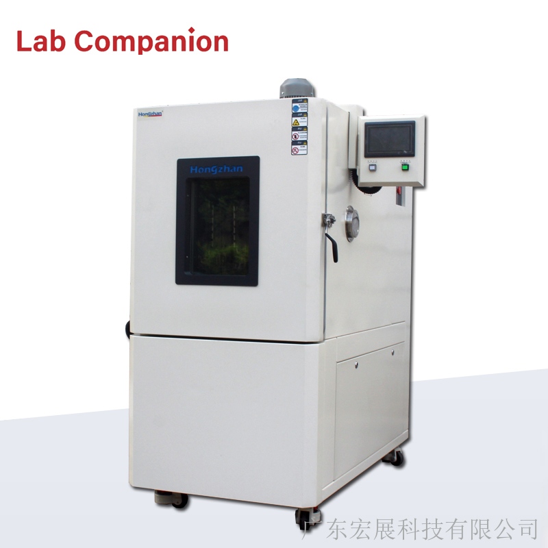
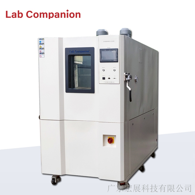
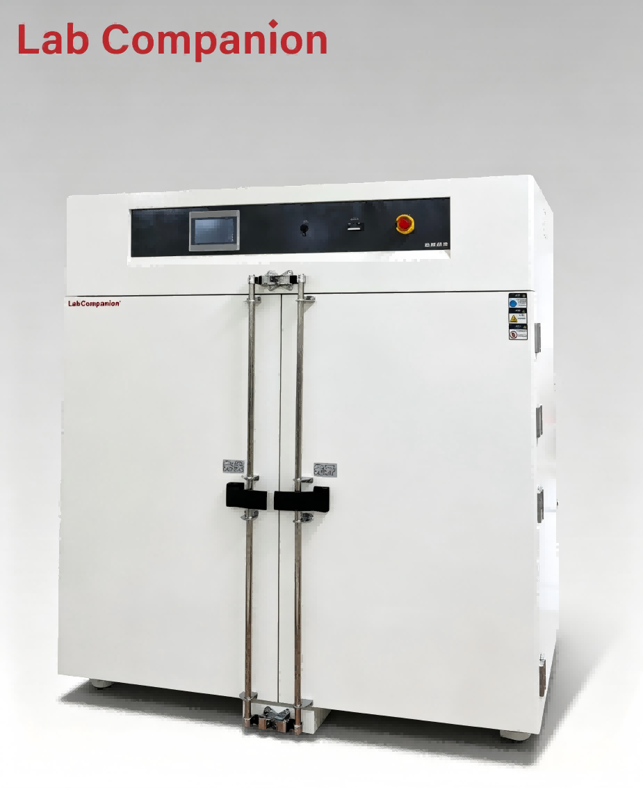
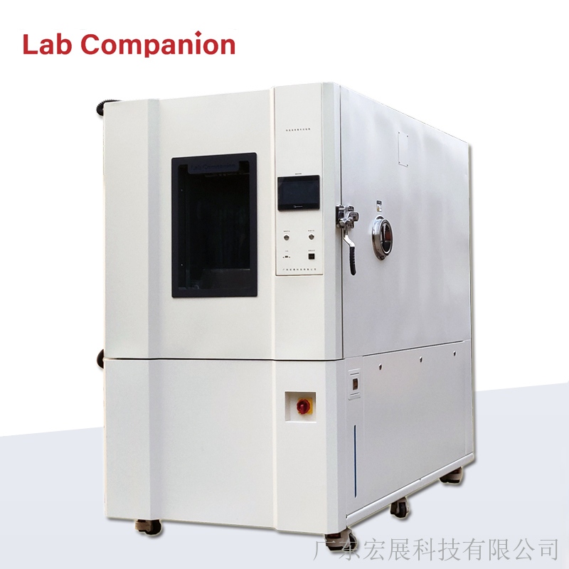
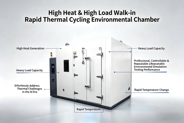
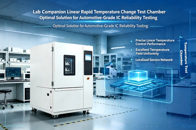

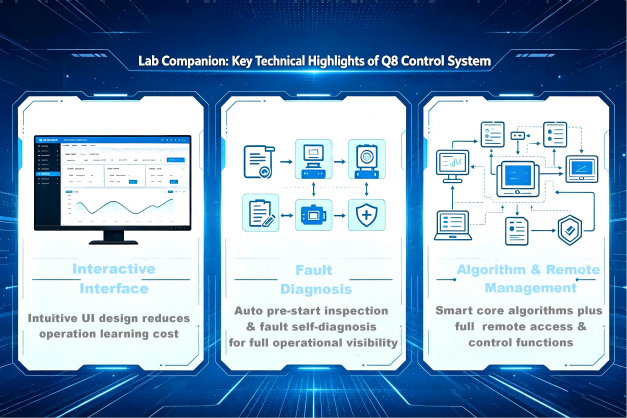
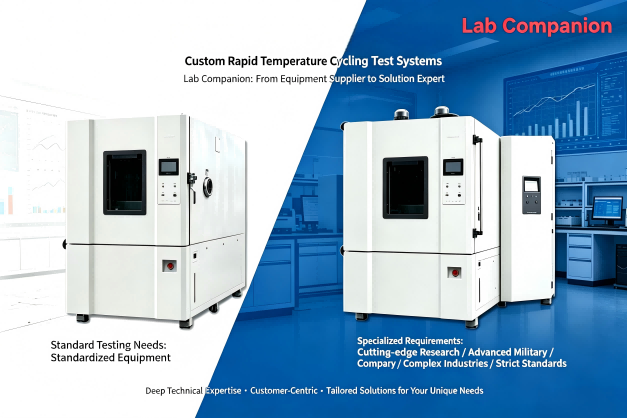


 Ein Angebot bekommen
 IPv6-Netzwerk unterstützt