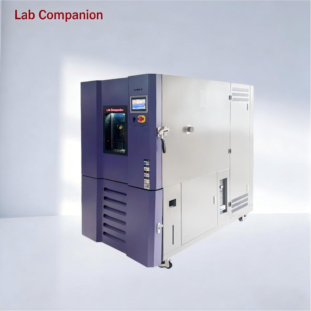
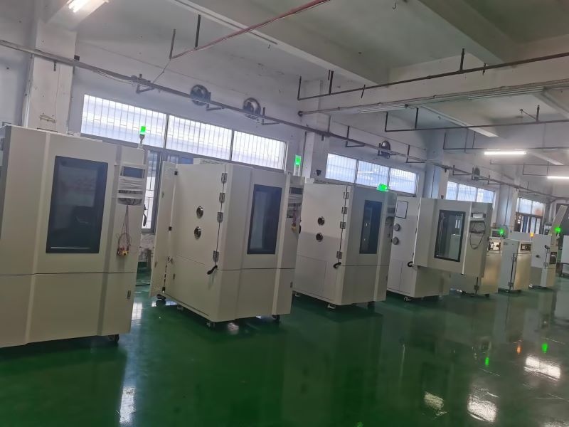
In industrial testing and scientific research, Lab Companion’s environmental test chambers are essential for product reliability verification, widely applied in electronics, automotive, aerospace, home appliances and other sectors. Both chambers focus on temperature range simulation and are easily confused in selection, yet differ sharply in core functions and application scenarios. This guide clarifies their key similarities, differences and scientific selection logic for optimal matching.
I. Key Commonalities
Both are artificial environmental simulation devices for evaluating product stability in extreme temperatures, providing data support for R&D, mass production testing and quality control, and complying with GB, IEC, ISO and other international standards.
1. Overlapping temperature range: -70℃~150℃ for high and low temperature chambers, -40℃~150℃ for constant temperature and humidity chambers, covering most industrial basic temperature test needs.
2. Unified operation & precision: Equipped with intelligent control systems (supporting parameter preset, curve programming, data export); temperature control accuracy ±0.5℃, fluctuation ≤±1℃.
II. Core Differences
The fundamental distinction is the presence of a humidity control module, which defines functional boundaries, application scenarios, structure, cost and O&M:
High and Low Temperature Test Chamber
1. Core Function: Only temperature regulation (heating/cooling/constant temperature), no humidity control module
2. Typical Scenarios: Temperature-only tests, e.g., high/low temperature cycle of electronic components, temperature impact of auto parts
3. Structure: Simplified configuration (heater, refrigeration system); better thermal insulation, smaller footprint for the same specification
4. Cost & O&M: Lower procurement cost; simple routine maintenance for refrigeration/heating system only, low energy consumption
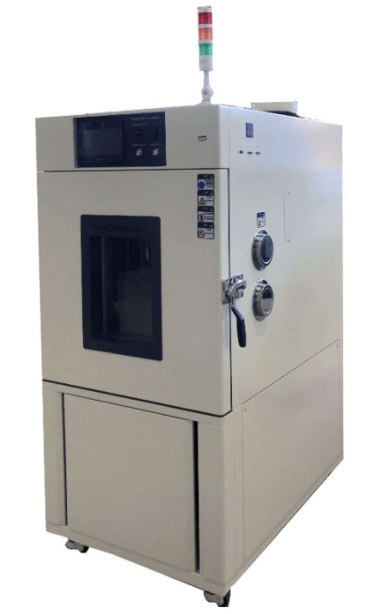
Constant Temperature and Humidity Test Chamber
1. Core Function: Dual regulation of temperature and humidity; humidity range 40%~95%RH (20%~98%RH for premium models), accuracy ±2%RH
2. Typical Scenarios: Temperature-humidity synergy tests, e.g., damp heat aging of electronics, humidity storage of medical devices, damp heat operation of home appliances
3. Structure: Complex configuration (humidification tank, dehumidifier, high-seal box); additional components for professional humidity control
4. Cost & O&M: 15%~30% higher procurement cost by specification; regular O&M for humidity parts (tank cleaning, sensor calibration), relatively higher energy consumption.
III. Selection Guide
Adhere to demand-oriented matching and balance cost performance with the following core principles:
1. Choose High and Low Temperature Test Chamber if: Only temperature change testing is needed, humidity has no impact on results, budget is limited, or laboratory space is narrow (high cost performance, easy O&M)
2. Choose Constant Temperature and Humidity Test Chamber if: Temperature-humidity synergy simulation is required, compliance with industry humidity test standards is needed, or testing moisture/corrosion-prone samples (focus on humidity parameters and reserve O&M budget)
IV. Conclusion
Lab Companion’s two test chambers both deliver stable temperature regulation for diverse industrial needs, with core differences rooted in the humidity control module. The high and low temperature chamber is ideal for basic temperature-only tests with its specialized function and cost efficiency; the constant temperature and humidity chamber excels in complex environmental simulation with its dual temperature-humidity regulation capability.
Abandon the misconception of "more functions = better". Optimal selection relies on integrating core test needs, budget, O&M capacity and laboratory space, to achieve the best balance between test effectiveness and long-term use cost. The two chambers complement each other, forming the core competitiveness of Lab Companion’s environmental test chamber series.
Der Schlüssel zur Schaffung einer sicheren Testumgebung für das Labor Hoch- und Niedertemperaturprüfkammer liegt in der Gewährleistung der persönlichen Sicherheit, der Gerätesicherheit, der Sicherheit der Prüflinge und der Datengenauigkeit.1. Überlegungen zur persönlichen SicherheitBevor Sie die Tür der Hochtemperaturkammer öffnen, um die Probe zu entnehmen, müssen Sie die hitze- und kältebeständige Schutzausrüstung ordnungsgemäß tragen. Bei Arbeiten, bei denen es zu Spritzern oder dem Austreten extrem heißer/kalter Gase kommen kann, wird das Tragen einer Schutzmaske oder Schutzbrille empfohlen.Die Prüfkammer sollte in einem gut belüfteten Labor aufgestellt werden. Der Betrieb in engen Räumen sollte vermieden werden. Bei Hochtemperaturprüfungen können flüchtige Substanzen aus dem Prüfling freigesetzt werden. Eine gute Belüftung kann die Ansammlung schädlicher Gase verhindern.Stellen Sie sicher, dass die Netzkabelspezifikationen den Geräteanforderungen entsprechen und das Erdungskabel zuverlässig angeschlossen ist. Vor allem ist es strengstens verboten, Netzstecker, Schalter und Proben mit nassen Händen zu berühren, um einen Stromschlag zu vermeiden. 2. Installieren Sie das Gerät richtigDer vom Hersteller angegebene Mindestsicherheitsabstand (normalerweise mindestens 50–100 Zentimeter) muss auf der Rückseite, Oberseite und beiden Seiten des Geräts eingehalten werden, um den normalen Betrieb des Kondensators, des Kompressors und anderer Wärmeableitungssysteme zu gewährleisten. Eine schlechte Belüftung kann zu Überhitzung, Leistungsabfall und sogar zu Bränden des Geräts führen.Es wird empfohlen, für die Prüfkammer eine eigene Stromleitung bereitzustellen, um zu vermeiden, dass derselbe Stromkreis mit anderen Hochleistungsgeräten (wie Klimaanlagen und großen Instrumenten) geteilt wird, was zu Spannungsschwankungen oder Auslösungen führen kann.Die empfohlene Umgebungstemperatur für den Betrieb des Geräts liegt zwischen 5 °C und 30 °C. Zu hohe Umgebungstemperaturen erhöhen die Belastung des Kompressors erheblich, was zu einer Verringerung der Kühlleistung und Fehlfunktionen führt. Bitte beachten Sie, dass das Gerät nicht in direkter Sonneneinstrahlung, in der Nähe von Wärmequellen oder an Orten mit starken Vibrationen installiert werden sollte. 3. Gewährleistung der Gültigkeit und Wiederholbarkeit von TestsDie Proben sollten mittig im Arbeitsraum der Box platziert werden. Zwischen den Proben und zwischen ihnen und der Boxwand sollte ausreichend Platz sein (üblicherweise mehr als 50 mm empfohlen), um eine reibungslose Luftzirkulation in der Box sowie eine gleichmäßige und stabile Temperatur zu gewährleisten.Nach der Durchführung von Tests bei hohen Temperaturen und hoher Luftfeuchtigkeit (z. B. in einer Kammer mit konstanter Temperatur und Luftfeuchtigkeit) sollten, wenn Tests bei niedrigen Temperaturen erforderlich sind, Entfeuchtungsvorgänge durchgeführt werden, um eine übermäßige Eisbildung in der Kammer zu verhindern, die die Leistung des Geräts beeinträchtigen könnte.Das Testen brennbarer, explosiver, hochätzender und leichtflüchtiger Stoffe ist strengstens verboten, mit Ausnahme von speziell für diesen Zweck entwickelten explosionsgeschützten Prüfkammern. Es ist strengstens verboten, gefährliche Güter wie Alkohol und Benzin in gewöhnlichen Hoch- und Niedertemperaturkammern zu lagern. 4. Sicherheitstechnische Betriebsvorschriften und NotfallmaßnahmenÜberprüfen Sie vor dem Betrieb, ob die Tür des Behälters gut abgedichtet ist und ob die Türverriegelung normal funktioniert. Überprüfen Sie, ob der Behälter sauber und frei von Fremdkörpern ist. Überprüfen Sie, ob die eingestellte Temperaturkurve (das Programm) korrekt ist.Während der Testphase muss regelmäßig überprüft werden, ob der Betriebszustand des Geräts normal ist und ob ungewöhnliche Geräusche oder Alarme auftreten.Handhabung und Platzierung der Probe: Tragen Sie bei hohen und niedrigen Temperaturen geeignete Handschuhe. Drehen Sie sich nach dem Öffnen der Tür leicht zur Seite, um zu vermeiden, dass die Hitzewelle Ihr Gesicht trifft. Entnehmen Sie die Probe schnell und vorsichtig und legen Sie sie an einen sicheren Ort.Notfallmaßnahmen: Machen Sie sich mit der Position des Not-Aus-Schalters des Geräts vertraut und wissen Sie, wie Sie im Notfall die Hauptstromversorgung schnell unterbrechen können. In der Nähe sollten Kohlendioxid-Feuerlöscher (geeignet für elektrische Brände) anstelle von Wasser- oder Schaumfeuerlöschern bereitgestellt werden.
Beim Betrieb einer Prüfkammer mit konstanter Temperatur und Luftfeuchtigkeit ist es wichtig, sich potenzieller Probleme bewusst zu sein und einen ordnungsgemäßen Betrieb sicherzustellen. Unsachgemäße Handhabung kann leicht zu Gerätestörungen führen. Im Laufe der Zeit treten jedoch zwangsläufig einige Fehler auf. In diesem Artikel besprechen wir einige häufige Fehler und deren Lösungen.Fehler: Erreicht die Temperatur beim Hochtemperaturtest nicht den Sollwert, ist zunächst die elektrische Anlage zu prüfen und die einzelnen Komponenten zu überprüfen. Steigt die Temperatur in der Prüfkammer mit konstanter Temperatur und Luftfeuchtigkeit zu langsam, prüfen Sie die Luftzirkulation und stellen Sie sicher, dass die Regelklappe ordnungsgemäß funktioniert. Steigt die Temperatur zu schnell, passen Sie die PID-Einstellungen an. Löst die Temperatur zu schnell den Übertemperaturschutz aus, ist möglicherweise der Regler defekt. Tauschen Sie in diesem Fall das Bedienfeld oder das Halbleiterrelais aus. Fehler: Wenn die Prüfkammer mit konstanter Temperatur und Luftfeuchtigkeit die Anforderungen für den Kältetest nicht erfüllt, prüfen Sie, ob die Temperatur sehr langsam abfällt oder sich an einem bestimmten Punkt stabilisiert, bevor sie wieder ansteigt. Falls die Temperatur sehr langsam abfällt, prüfen Sie, ob die Kammer vor dem Kältetest getrocknet wurde, um die Trockenheit zu gewährleisten. Stellen Sie sicher, dass die Proben nicht zu dicht platziert sind, um eine unzureichende Luftzirkulation zu verhindern. Nachdem Sie diese Probleme ausgeschlossen haben, prüfen Sie, ob das Kühlsystem defekt ist. Wenden Sie sich in diesem Fall an den Hersteller, um eine professionelle Reparatur zu erhalten. Störung: Sollte die Prüfkammer für konstante Temperatur und Luftfeuchtigkeit während des Betriebs eine Störung aufweisen und auf dem Bedienfeld eine Fehlermeldung und ein akustisches Signal ausgegeben werden, kann der Bediener im Abschnitt zur Fehlerbehebung in der Bedienungsanleitung des Geräts nachsehen, um die Art der Störung zu ermitteln. Professionelles Wartungspersonal sollte dann die notwendigen Reparaturen durchführen, um einen reibungslosen Testablauf zu gewährleisten. Bei anderen Umweltexperimentiergeräten treten im Betrieb andere Bedingungen auf, die je nach Situation behandelt werden müssen.
1.GeräteübersichtDie Feuchte- und Temperaturprüfkammer, auch bekannt als Umweltsimulationsprüfgerät, ist ein Präzisionsgerät, das die strikte Einhaltung von Betriebsprotokollen erfordert. Als elektrisches Gerät der Klasse II gemäß Sicherheitsnorm IEC 61010-1 sind seine Zuverlässigkeit (±0,5 °C Temperaturstabilität), Präzision (±2 % relative Luftfeuchtigkeitsgenauigkeit) und Betriebsstabilität entscheidend für die Erzielung von ISO/IEC 17025-konformen Testergebnissen.2. Sicherheitsprotokolle vor der Operation2.1 Elektrische Anforderungen Stromversorgung: 220 V AC ±10 %, 50/60 Hz mit unabhängiger Erdung (Erdungswiderstand ≤4 Ω) Not-Aus-Schaltung und Überstromschutz installieren (empfohlen 125 % des Nennstroms) Implementieren Sie einen RCD (Residual Current Device) mit einem Auslösestrom von ≤30 mA2.2 Installationsspezifikationen Freigabeanforderungen: Hinten: ≥500mm Seitlich: ≥300mm Vertikal: ≥800mm Umgebungsbedingungen: Temperatur: 15-35°C Luftfeuchtigkeit: ≤85 % relative Luftfeuchtigkeit (nicht kondensierend) Luftdruck: 86-106 kPa 3.Betriebliche Einschränkungen3.1 Verbotene Umgebungen Explosive Atmosphären (ATEX Zone 0/20 verboten) Korrosive Umgebungen (HCl-Konzentration > 1 ppm) Gebiete mit hohem Feinstaubanteil (PM2,5 >150μg/m³)Starke elektromagnetische Felder (>3V/m bei 10kHz-30MHz)4. Inbetriebnahmeverfahren4.1 Checkliste vor dem Start Überprüfen Sie die Integrität der Kammer (strukturelle Deformation ≤0,2 mm/m). Bestätigen Sie die Gültigkeit der PT100-Sensorkalibrierung (NIST-rückführbar) Kältemittelstand prüfen (R404A ≥85 % der Nennfüllung) Validierung der Neigung des Entwässerungssystems (≥3° Gefälle)5.Betriebsrichtlinien5.1 Parametereinstellung Temperaturbereich: -70°C bis +150°C (Gradient ≤3°C/min) Feuchtigkeitsbereich: 20 % RH bis 98 % RH (Taupunktüberwachung erforderlich >85 % RH) Programmschritte: ≤120 Segmente mit Ramp-Soak-Steuerung 5.2 Sicherheitsverriegelungen Tür-Offen-Abschaltung (Aktivierung innerhalb von 0,5s) Übertemperaturschutz (zwei redundante Sensoren) Erkennung eines Feuchtigkeitssensorfehlers (Aktivierung des Auto-Dry-Modus)6.Wartungsprotokoll6.1 Tägliche Wartung Reinigung der Kondensatorspule (Druckluft 0,3–0,5 MPa) Prüfung des Wasserwiderstands (≥1MΩ·cm) Türdichtungsprüfung (Leckrate ≤0,5 % Vol./h) 6.2 Regelmäßige Wartung Kompressorölanalyse (alle 2.000 Stunden) Druckprüfung des Kältemittelkreislaufs (jährlich) Kalibrierzyklus: Temperatur: ±0,3°C (jährlich) Luftfeuchtigkeit: ±1,5 % relative Luftfeuchtigkeit (halbjährlich)7.FehlerreaktionsmatrixSymptomprioritätPrioritätSofortmaßnahmenTechnische AntwortUnkontrollierte ErwärmungP1Not-Aus aktivierenÜberprüfen Sie den SSR-Betrieb (Vf
Um die gewünschten Testbedingungen in einer konstanten Temperatur- und Luftfeuchtigkeitstestkammer zu erreichen, ist es unvermeidlich, Luftbefeuchtungs- und Entfeuchtungsoperationen durchzuführen. Dieser Artikel analysiert die verschiedenen Methoden, die üblicherweise in Labcompanonionstemperatur- und Feuchtigkeitstestkammern verwendet werden und ihre jeweiligen Vor-, Nachteile und empfohlenen Bedingungen für die Verwendung hervorheben.Feuchtigkeit kann in vielerlei Hinsicht ausgedrückt werden. Für Testgeräte ist die relative Luftfeuchtigkeit das am häufigsten verwendete Konzept. Die relative Luftfeuchtigkeit ist definiert als das Verhältnis des Partialdrucks von Wasserdampf in der Luft zum Sättigungsdampfdruck von Wasser bei derselben Temperatur, die als Prozentsatz ausgedrückt wird.Aus den Eigenschaften des Wasserdampfsättigungsdrucks ist bekannt, dass der Sättigungsdruck des Wasserdampfes ausschließlich eine Funktion der Temperatur ist und unabhängig vom Luftdruck ist, bei dem der Wasserdampf existiert. Durch umfangreiche Experimente und Datenorganisation wurde die Beziehung zwischen Wasserdampfsättigungsdruck und Temperatur hergestellt. Unter diesen wird die Goff-Grat-Gleichung in Engineering und Metrologie weit verbreitet und derzeit von meteorologischen Abteilungen verwendet, um Feuchtigkeitsreferenztabellen zu erstellen.Befeuchtungsprozess Die Befeuchtung beinhaltet im Wesentlichen die Erhöhung des Teildrucks von Wasserdampf. Die früheste Methode der Befeuchtung bestand darin, Wasser auf die Kammerwände zu sprühen und die Wassertemperatur zu steuern, um den Oberflächensättigungsdruck zu regulieren. Das Wasser an den Kammerwänden bildet eine große Oberfläche, durch die Wasserdampf in die Kammer diffundiert und die relative Luftfeuchtigkeit im Inneren erhöht. Diese Methode entstand in den 1950er Jahren. Zu diesem Zeitpunkt wurde die Feuchtigkeitskontrolle hauptsächlich unter Verwendung von Quecksilberkontaktleitfähigkeitszählern für eine einfache Ein-Aus-Regulierung erreicht. Diese Methode war jedoch schlecht geeignet, um die Temperatur großer, verzögerungsanfälliger Wassertanks zu kontrollieren, was zu langen Übergangsprozessen führte, die den Anforderungen wechselnder Feuchtigkeitstests, die eine schnelle Befeuchtung erfordern, nicht gerecht werden konnten. Noch wichtiger ist, dass das Sprühen von Wasser auf die Kammerwände unvermeidlich zu Wassertröpfchen auf die Testproben führte, was zu unterschiedlichen Kontaminationsgraden führte. Darüber hinaus stellte diese Methode bestimmte Anforderungen für die Entwässerung innerhalb der Kammer auf. Diese Methode wurde bald durch Dampfbefeuchtung und Befeugung der flachen Wasserpfanne ersetzt. Es hat jedoch immer noch einige Vorteile. Obwohl der Kontrollübergangsprozess langwierig ist, sind die Luftfeuchtigkeitsschwankungen minimal, sobald sich das System stabilisiert, sodass es für konstante Luftfeuchtigkeitstests geeignet ist. Darüber hinaus wird während des Befeuchtungsprozesses der Wasserdampf nicht überhitzt, wodurch die Zugabe von zusätzlicher Wärme zum System vermieden wird. Wenn die Sprühwassertemperatur als niedriger als die erforderliche Testtemperatur gesteuert wird, kann das Sprühwasser als Entfeugerer wirken. Entwicklung von Befeuchtungsmethoden Mit der Entwicklung der Feuchtigkeitstests von konstanter Luftfeuchtigkeit bis hin zur alternierenden Luftfeuchtigkeit enthielt sich die Notwendigkeit einer schnelleren Befeuchtungsreaktionsfunktionen. Sprühfeuchtigkeit konnte diese Anforderungen nicht mehr erfüllen, was zu der weit verbreiteten Einführung und Entwicklung von Dampfbefeuchtung und flachen Wasserpfannenbefeuchtungsmethoden führte. Dampfbefeuchtung Die Dampfbefeugung beinhaltet die Injektion von Dampf direkt in die Testkammer. Diese Methode bietet schnelle Reaktionszeiten und eine präzise Kontrolle über die Luftfeuchtigkeitsniveau, wodurch sie ideal für wechselnde Luftfeuchtigkeitstests ist. Es erfordert jedoch eine zuverlässige Dampfquelle und kann zusätzliche Wärme in das System einführen, die möglicherweise in temperaturempfindlichen Tests kompensiert werden müssen. Flachwasserpfanne Befeugung Die Luftwanne der flachen Wasserpfanne verwendet eine erhitzte Wasserpfanne, um Wasser in die Kammer zu verdampfen. Diese Methode liefert ein stabiles und konsistentes Feuchtigkeitsniveau und ist relativ einfach zu implementieren. Es kann jedoch langsamere Reaktionszeiten im Vergleich zur Dampfbefeuchtung aufweisen und erfordert regelmäßige Wartung, um Skalierung und Kontamination zu verhindern. Entfeuchtungsprozess Die Entfeuchtung ist der Prozess der Reduzierung des Teildrucks von Wasserdampf in der Kammer. Dies kann durch Kühl-, Adsorptions- oder Kondensationsmethoden erreicht werden. Bei der Kühlentfeuchtung werden die Temperatur der Kammer um den dann entfernten Wasserdampf verringert. Die Adsorptionsentfeuchte verwendet Trockenmittel, um Feuchtigkeit aus der Luft zu absorbieren, während die Kondensationsentfeugung auf Kühlspulen beruht, um Wasserdampf zu kondensieren und zu entfernen. Abschluss Zusammenfassend lässt sich sagen, dass die Auswahl der Befeuchtungs- und Entfeuchtungsmethoden in konstanten Temperatur- und Feuchtigkeitstestkammern von den spezifischen Anforderungen der durchgeführten Tests abhängt. Während ältere Methoden wie Spray -Befeuchtung ihre Vorteile haben, bieten moderne Techniken wie Dampfbefeuchtung und flache Wasserpfanne die Befeuchtung mehr Kontrolle und schnellere Reaktionszeiten, wodurch sie für fortschrittliche Testbedürfnisse geeigneter werden. Das Verständnis der Prinzipien und Kompromisse jeder Methode ist entscheidend für die Optimierung der Testkammerleistung und die Gewährleistung genauer und zuverlässiger Ergebnisse.
Einstellung und Wartung der Testkammer für konstante Temperatur und LuftfeuchtigkeitPrüfkammer für konstante Temperatur und Luftfeuchtigkeit ist ein relativ präzises Prüfgerät. Um einen reibungslosen Abschluss jedes Testvorgangs zu gewährleisten, muss die Stromversorgung der angeschlossenen Geräte stabil bei etwa 380 V liegen, um sicherzustellen, dass der Kompressor nicht beschädigt wird. Darüber hinaus müssen Sie die persönliche Sicherheit des Personals gewährleisten, das den Strom erhält. Machen Sie sich daher vor der Verkabelung mit den spezifischen Betriebsmethoden vertraut.Die Prüfkammer für konstante Temperatur und Luftfeuchtigkeit passt das angeschlossene Netzteil an oder ersetzt es. Nachdem Sie überprüft haben, dass die Spannung der anzuschließenden Stromversorgung korrekt ist, verbinden Sie den Neutralleiteranschluss mit dem Neutralleiteranschluss in der Verteilerkammer. Stellen Sie sicher, dass der Neutralleiter angeschlossen ist. Andernfalls kann es dazu kommen, dass die Ausrüstung der Prüfkammer für konstante Temperatur und Luftfeuchtigkeit nicht normal funktioniert oder elektrische Komponenten durchbrennen.Nachdem Sie sich vergewissert haben, dass der Neutralleiter angeschlossen ist, schließen Sie den 3∮-Draht an die drei Klemmen unter dem Hauptschalter der Verteilerkammer in der Testkammer für konstante Temperatur und Luftfeuchtigkeit an und ziehen Sie die Schrauben fest. Wir müssen das Erdungskabel, das auf die gleiche Weise wie andere Stromkabel angeschlossen wird, direkt an die Erdungsklemme der Verteilerkammer anschließen. Beim Anschließen jedes Netzkabels muss jeder sicherstellen, dass die verschiedenen Farben des Netzkabels korrekt identifiziert werden können, um Verbindungsfehler und normale Tests zu vermeiden.Wartung der Testkammer mit konstanter Temperatur und Luftfeuchtigkeit:1, Reinigen Sie das Wasserzirkulationssystem: Reinigen Sie den Wasserfilter, tauschen Sie den Filter aus, überprüfen Sie die Funktion der Pumpe, einschließlich der Funktion des Wasserdurchflussschalters, stellen Sie den Wasserzirkulationsfluss ein und testen Sie den Betrieb.2. Überprüfen Sie alle elektrischen Leitungen und elektrischen Komponenten, um einen zuverlässigen Betrieb und guten Kontakt sicherzustellen.3. Ersetzen Sie den Frischluftfilter.4, Reinigung des Kühlsystems: Ersetzen Sie das Kühlöl und reinigen Sie den Ölfilter.5. Überprüfen Sie die gefährdeten Teile des Kühlsystems: Überprüfen Sie den Dichtungszustand des Kompressors und der Verbindungsteile und ersetzen Sie alle Filter.6, Leckprüfung des Kühlsystems: Überprüfen Sie, ob alle Verbindungsteile des Kühlsystems und die Verbindungsteile der Ventilplatte undicht sind und festgezogen sind.7. Abhängig von den Arbeitsbedingungen zur Ergänzung des Kältemittels: Prüfen Sie, ob eine Ergänzung des Systemkältemittels erforderlich ist, um eine effektive Kühlleistung sicherzustellen.8, Umfassender Systembetrieb: Überprüfen Sie, ob die Betriebskomponenten in gutem Zustand sind.
Wartungsmethode der Hoch- und Niedertemperatur-TestkammerEs gibt drei gängige Arten von Prüfkammer für hohe und niedrige Temperaturen Controller: Softwarefehler, Systemfehler und Hardwarefehler.1, Softwarefehler: Softwarefehler beziehen sich hauptsächlich auf den Controller-Fehler der Hoch- und Niedertemperatur-Testkammer, einschließlich der internen Parameter, der IS-Steuerung des Steuerpunkts und des Ausgangssignals des Ein- und Ausschaltens des Magnetventils.2, Systemfehler: Ein Systemausfall bezieht sich auf die anfänglichen Konstruktionsprobleme des Kühlsystems, einschließlich des Austretens von Kältemittel, das dadurch verursacht wird, dass die Prüfkammer bei hohen und niedrigen Temperaturen nicht abkühlt, und Kältemittellecks sind häufig auf Transport und Betriebsschwankungen der Prüfkammer bei hohen und niedrigen Temperaturen oder auf Kühlung zurückzuführen Der Kupferrohrschweißprozess ist nicht in Ordnung und es gibt andere Gründe dafür.3, Hardwarefehler: Ein Hardwarefehler kann dazu führen, dass der Kompressor, das Magnetventil und andere Kühlkomponenten nicht kühlen.Dann kann der Benutzer zuhören und anfassen, um grob zu verstehen, was die Hardware-Schäden in der Testkammer bei hohen und niedrigen Temperaturen sind. Wenn es sich um einen Kompressorausfall handelt, ist das Kompressorgeräusch ungewöhnlich oder funktioniert nicht, startet nicht oder die Temperatur des Kompressors selbst ist viel höher als übliche Temperatur, und der Ausfall des Magnetventils und anderer Kühlkomponenten ist für den Benutzer nicht allzu gut, um ihn zu meistern.Darüber hinaus kann die Beschädigung des Controllers und die Beschädigung der elektronischen Teile des Kühlsystems zur Steuerung auch das Phänomen der Nichtkühlung und Nichtkühlung der Hoch- und Niedertemperatur-Testkammer verursachen.Wissenschaftliches Prinzip des Heizens und Kühlens von Hoch- und Niedertemperatur-Testkammern:Die Testkammer für hohe und niedrige Temperaturen hat die Funktionen Heizen, Kühlen, Befeuchten und Entfeuchten und kann die hohe Temperaturbeständigkeit, niedrige Temperaturbeständigkeit und Feuchtigkeitsbeständigkeit des Produkts erkennen. Wie wird die Temperatur in der Hoch- und Niedertemperatur-Prüfkammer gesteuert?Das Heizgerät ist das zentrale Glied zur Steuerung, ob die Hoch- und Niedertemperatur-Prüfkammer aufgeheizt wird. Der Regler gibt Spannung an das Relais aus, wenn er den Heizbefehl erhält. In der Testkammer für hohe und niedrige Temperaturen werden dem Halbleiterrelais etwa 3–12 Volt Gleichstrom zugeführt. Das AC-Ende der Hoch- und Niedertemperatur-Prüfkammer entspricht einer Drahtverbindung, und gleichzeitig wird auch das Schütz gezogen. Heizen Sie die Testkammer mit konstanter Temperatur und Luftfeuchtigkeit auf.Die Kühlung ist ein wichtiger Teil der Testkammer für hohe und niedrige Temperaturen, der sich direkt auf die Bestimmung der hohen und niedrigen Temperatur und der Leistung auswirkt. Dazu gehören Kompressor, Kondensator, Drosselvorrichtung und Verdampfer. Die vier Hauptkomponenten sind der Kompressor und das Herzstück des Kühlsystems. Es inhaliert Gas mit niedriger Temperatur und niedrigem Druck in Gas mit hoher Temperatur und hohem Druck, durch Kondensation in eine Flüssigkeit, um Wärme freizusetzen, und durch den Ventilator, um Wärme abzuführen. Daher ist die Testkammer der Grund für heiße Luft und wird dann niedrig Druckflüssigkeit Durch Drosselung wird dann Gas mit niedriger Temperatur und niedrigem Druck durch den Verdampfer zurück zum Kompressor geleitet, wobei das Kältemittel im Verdampfer die Wärme der Hoch- und Niedertemperaturkammer aufnimmt, um den Vergasungsprozess abzuschließen und Wärme zu absorbieren, um den Zweck zu erreichen Kühlung, um den Kühlprozess der Testkammer bei hohen und niedrigen Temperaturen abzuschließen.Testverfahren für Hoch- und Niedertemperaturkammertemperatur und Abkühlrate:Im einstellbaren Temperaturbereich der Prüfkammer wurde als niedrigste Kühltemperatur die niedrigste Solltemperatur und als höchste Heiztemperatur die höchste Solltemperatur gewählt.Öffnen Sie die Kältequelle, so dass die Prüfkammer während des Erhitzens von Raumtemperatur auf die niedrigste Kühltemperatur, stabil für mindestens 3 Stunden, auf die höchste Heiztemperatur, stabil für mindestens 3 Stunden, und dann auf die niedrigste Kühltemperatur ansteigt und Abkühlung, einmal pro Minute bis zum Ende des Testvorgangs aufzeichnen.Das Prinzip der Hoch- und Niedertemperatur-Prüfkammerheizung und -kühlung besteht darin, dass die Verwirklichung ihrer Funktion durch die Einstellung des Steuerungssystems vervollständigt wird, wobei das Prinzip der Heiz- und Kühlkammer bei der Verwendung von Hoch- und Niedertemperatur-Prüfkammern verstanden werden muss praktischer.
Zusammensetzung der elektrischen Komponenten der Hoch- und Niedertemperatur-Testkammer
Die Hauptteile der Hoch- und Niedertemperaturtest Kammer sind Kühlaggregate, Kondensatoren, Verdampfer und Regler. Die Hauptbestandteile spielen eine Schlüsselrolle, daher achtet jeder besonders auf seine Hauptbestandteile, die Rohstoffe. Die meisten von ihnen ignorieren derzeit jedoch die Hilfsteile oder sind der Meinung, dass die Rolle der Hilfsteile nicht erwähnenswert ist. Nur wenige Menschen möchten die spezifischen Teile zählen, daher ist nicht klar, welche spezifischen elektronischen Komponenten in der Testkammer mit konstanter Temperatur und Luftfeuchtigkeit vollständig verwendet werden.
1, Kühleinheit:
Wird zur Steuerung des Betriebs der Kühleinheit und zur Durchführung des Kühlkreislaufs verwendet und ist in einphasiger und dreiphasiger Ausführung erhältlich.
2, Lüftermotor:
Wird zur Steuerung der Ventilatorzirkulation, des Dampfkörpers und der Wärmeleitung des Wärmetauschers verwendet und ist sowohl im Innen- als auch im Außenbereich erhältlich.
3, elektrische Heizgeräte:
Wird zum Heizen von Raumluftqualität, röhrenförmigen, flockigen Punkten verwendet.
4, Timer:
Wird für den Bootvorgang des automatischen Steuerungssystems verwendet.
5, DC-Schütz:
Wird zum Unterbrechen und Anschließen des Motors einer Kühleinheit verwendet.
6, Auslaufschutz-Netzschalter:
Es kann nicht nur den Hauptstromkreis wie andere Schalter verbinden oder trennen, mit dem Effekt der Leckstromerkennung und -unterscheidung, wenn der Hauptsteuerstromkreis durch Stromausfall oder Kabelmantelbeschädigung verursacht wird, kann der Hauptschalter der Stromversorgung des Leckschutzschalters angeschlossen oder getrennt werden Wechseln Sie die Komponenten entsprechend den Identifikationsergebnissen. Es kann mit einem Trennschalter und einem Wärmerelais kombiniert werden, um ein voll funktionsfähiges elektronisches Niederspannungsschaltgerät zu bilden.
7, Übertemperaturschutzausrüstung:
Seine Rolle kann nicht ignoriert werden, wenn die Temperatur des Controllers nicht empfindlich ist, die Implementierung der E-doppelten Aufrechterhaltung der Box-Übertemperatur, wenn der Alarm verursacht wird, die Wartungsbereitschaft, der Alarm unterscheidet sich von der Testtemperatur, der relativen Änderung, Sie können außerdem die Rolle der Übertemperaturaufrechterhaltung übernehmen. Das Grundkonzept besteht darin, dass, wenn der Gesamtstromfluss des gebrochenen Drahtes den Grenzwert überschreitet, die Temperatur des gebrochenen Drahtes ansteigt und der gebrochene Draht bricht. Wenn der durch den gebrochenen Draht verursachte Wärmewert seine Kurzschlusskapazität nicht überschreitet, ist das Gleichgewicht zwischen dem Wärmewert und dem freigesetzten Wärmewert gewährleistet, die Temperatur des gebrochenen Drahtes kann die Schmelztemperatur nicht erreichen und es ist nicht leicht, ihn zu brechen.
Solche kleinen elektronischen Komponenten sehen in der Hoch- und Niedertemperatur-Testkammer harmlos aus, aber für die Struktur einer Testkammer ist sie auch sehr nützlich. Ohne diese Komponenten kann eine Testkammer nicht verwendet werden, kurz gesagt, die Details bestimmen das Erfolg des Scheiterns, fein ohne Größe, gleichzeitig im Griff der Testkammer, sollte mehr von seinen Schlüsselgliedern zu erfassen sein.
Beleuchtungsinstallationsposition der Testkammer für hohe und niedrige TemperaturenEntsprechend den unterschiedlichen Bedürfnissen der Benutzer ist die Einbauposition der Lampe im Hoch- und Niedertemperaturlabor unterschiedlich. Die Prüfkammer für konstante Temperatur und Luftfeuchtigkeit testet die Hitzebeständigkeit, Kältebeständigkeit, Trockenbeständigkeit und Feuchtigkeitsbeständigkeit verschiedener Materialien. Geeignet für die Elektronik-, Elektro-, Lebensmittel-, Fahrzeug-, Metall-, Chemie-, Baustoff- und andere Branchen der Qualitätskontrolle. Diese Produktserie eignet sich für Luft- und Raumfahrtprodukte, informationselektronische Instrumente, Materialien, elektrische, elektronische Produkte und verschiedene elektronische Komponenten in Umgebungen mit hohen und niedrigen Temperaturen oder Temperatur und Luftfeuchtigkeit, um die verschiedenen Leistungsindikatoren zu testen.Die gebräuchlichsten Temperaturprüfgeräte sind Umweltprüfgeräte und ähnliche verwandte Produkte Wechselprüfkammer mit hoher und niedriger Temperatur, Testkammer für konstante Temperatur und Luftfeuchtigkeit, Testkammer für hohe und niedrige Temperatur und Luftfeuchtigkeit und so weiter. Es eignet sich für die Zuverlässigkeitsprüfung von Industrieprodukten bei hohen und niedrigen Temperaturen. Begehbare Testkammer für hohe und niedrige Temperaturen, begehbare Testkammer für hohe und niedrige Temperaturen wird für thermische Tests in der nationalen Verteidigungsindustrie, der Luft- und Raumfahrtindustrie, automatischen Komponenten, Automobilteilen, elektronischen und elektrischen Teilen, Kunststoffen, der chemischen und pharmazeutischen Industrie usw. verwendet verwandte Produkte. Es bietet große Teile, Halbzeuge und große Temperatur- und Feuchtigkeitstestumgebungen für Fertigprodukte. Es eignet sich für Testgeräte mit großer Menge und Volumen.Einige sind an der Innenkammer oder Tür angebracht, andere nicht. Wo kann man Glühbirnen am besten installieren?Tatsächlich hat die Beleuchtung der Hoch- und Niedertemperatur-Prüfkammer unabhängig vom Installationsort Vor- und Nachteile.Wenn die Beleuchtung im Senderaum installiert ist, können Sie den Zustand des gesamten Senderaums klar erkennen und das Produkt jederzeit beobachten.Die Lampe ist an der Tür installiert, und wenn der Benutzer den Doppel-85-Test oder den Test bei hoher Temperatur und hoher Luftfeuchtigkeit durchführt, kann die Feuchtigkeit nicht leicht in die Lampe eindringen und die Lampe kann nicht leicht beschädigt werden, was die Temperatur erheblich verringern kann Kundendienstgebühr. Allerdings ist sein Beobachtungsfeld sehr klein, es kann nur die nahegelegenen Sehenswürdigkeiten beobachten, und die Kunden beobachten, dass das Produkt nicht sehr praktisch ist.Wenn die Lampe auf der rechten Seite der Innenkammer installiert wird, wird empfohlen, sie vollständig abzudichten, um das Eindringen von Feuchtigkeit zu verhindern und einen langfristig stabilen Betrieb der Lampe zu gewährleisten. Bei der Montage an einer Tür empfiehlt es sich, das Sichtfenster trapezförmig zu gestalten, damit Sie ein größeres Sichtfeld haben.Natürlich entscheiden sich einige Firmenkunden beim Kauf von Hoch- und Niedertemperatur-Prüfkammern dafür, keine Beleuchtung zu installieren, um die Produktionskosten und späteren Verwaltungskosten zu senken. Allerdings können Kunden bei der Durchführung von Tests zu keinem Zeitpunkt Produkte beobachten, und sie können nicht auf die Bedürfnisse verschiedener Kunden eingehen, die Produkte beobachten möchten.
Dichtungsprobleme und Lösungen von Testkammern für hohe und niedrige TemperaturenPrüfkammer für hohe und niedrige Temperaturen basiert auf der natürlichen Umgebung wie hoher Temperatur, extrem niedriger Temperatur, hoher und niedriger Temperatur und Trocknung bei niedriger Temperatur im Raum während der Bauarbeiten und führt dann Tests bei hohen und niedrigen Temperaturen sowie Experimente zur Temperatur- und Feuchtigkeitsalterungsbeständigkeit durch Der Rohstoff wird hauptsächlich für Industrieprodukte wie Elektronik und Elektrik, Instrumentierungsausrüstung, Autos und Motorräder, Universitäten und andere Fertigungsindustrien verwendet.Aufgrund von Hochtemperaturprüfungen, Ultratieftemperaturprüfungen, Hoch- und Niedertemperaturtestzyklussystemtests, Hoch- und Niedertemperaturtests und anderen experimentellen Standards werden Hoch- und Niedertemperaturtestkammern in den Hochtemperaturstandards eingesetzt, z. B. bei 150 ° C-Extremität Wenn sich die Bedingungen bei hoher Temperatur und 98 % der Umgebungsfeuchtigkeit sowie der Druckunterschied zwischen innerhalb und außerhalb des Labors erheblich vergrößern, ist in diesem Moment die Dichtwirkung der Testkammer wirklich wichtig. Wenn die Luftdichtheit nicht sehr gut ist, kommt es zu stärkeren Dampflecks, was die Präzision und Genauigkeit der Temperatur beeinträchtigt.Welche Faktoren verursachen das Dichtungsproblem der Hoch- und Niedertemperatur-Prüfkammer?Erstens verfügt die Prüfkammer für konstante Temperatur und Luftfeuchtigkeit normalerweise über Kabellöcher und Abluftlöcher, und das Designschema ist sehr streng.Wenn das Entwurfsschema und die Produktion nicht wissenschaftlich sind, ist die Lücke zu groß und die Abdichtung der Umwelttestkammer ist nicht gut. Dieses Stanzstudio sollte auch daran denken, die entsprechenden Spezifikationen des Flaschenverschlusses, Gummistopfens usw. zu verschließen, um sicherzustellen, dass die Abdichtung dieser Stanzstelle intakt ist.Zweitens das Problem der Abdichtung der Gummistreifen der Hoch- und Niedertemperatur-Prüfkammer. Normalerweise ignorieren wir dieses Problem und sind der Meinung, dass der Dichtungsstreifen dem Türscharnier hinzugefügt wird und unter der Hemmung des Türscharniers sehr gut abdichten sollte, da die Silikondichtung altert, die Auswahl der harten Flexibilität unwissenschaftlich ist und die Abdichtung Der Streifen ist fest und nicht gleich, was häufig zu Dampflecks führt. Es ist auch einfach zu handhaben, oft wird die Dichtheit getestet und es wird festgestellt, dass die Versprödung des Dichtungsstreifens so schnell wie möglich ersetzt werden muss.Drittens, da das Gesamtvolumen der Hoch- und Niedertemperatur-Testkammer relativ groß ist, werden die Spezifikationen der Hecktür erweitert, das Nettogewicht ist sehr groß und die vertikale Ausrichtung des Türscharniers wird nach der Langzeitbelastung versetzt. und die Hecktür wird verschoben und geschlossen. Solche Probleme werden in der Regel anhand der modifizierten Hochlast-Türscharniere und der Gesamtzahl der Türscharniere behandelt.Aus der obigen Analyse ist ersichtlich, dass das Dichtungsproblem der Hoch- und Niedertemperatur-Testkammer einige Konstruktionsprobleme und einige Wartungsprobleme mit sich bringt. Daher sollten wir uns strikt an das Gerätewartungshandbuch für die regelmäßige Wartung der Geräte halten, um den normalen Betrieb der Geräte und keine Abweichungen der technischen Parameter sicherzustellen.
Grundsätze, denen der Betrieb einer Testkammer mit konstanter Temperatur und Luftfeuchtigkeit folgen sollte Prüfkammer für konstante Temperatur und Luftfeuchtigkeit, auch bekannt als Prüfgerät für konstante Temperatur und Luftfeuchtigkeit, Wechselprüfkammer mit programmierbarer Temperatur und Luftfeuchtigkeit, Thermostat oder Kammer für konstante Temperatur und Luftfeuchtigkeit, kann zum Testen verschiedener Umgebungen und zum Testen der Materialleistung von Geräten verwendet werden. Dieses Material weist Hitzebeständigkeit, Kältebeständigkeit und Trockenheit auf Beständigkeit und Feuchtigkeitsbeständigkeit. Bei Verwendung der Testkammer mit konstanter Temperatur und Luftfeuchtigkeit hilft jedoch die korrekte Bedienung dabei, wissenschaftliche Daten für den Experimentator zu erhalten. Welche Grundsätze sollten also beim Betrieb der Testkammer mit konstanter Temperatur und Luftfeuchtigkeit befolgt werden?u200eErstens muss der Bediener bei der Umweltprüfung mit der erforderlichen Prüfmusterleistung, den Prüfbedingungen, den Prüfverfahren und der Prüftechnik vertraut sein, mit der technischen Leistung der verwendeten Prüfgeräte vertraut sein und insbesondere den Aufbau der Geräte verstehen mit der Kontrolle, Bedienung und Leistung. Lesen Sie gleichzeitig die Bedienungsanleitung des Testgeräts sorgfältig durch, um einen abnormalen Betrieb des Testgeräts aufgrund von Bedienungsfehlern zu vermeiden, der zu Schäden am Testmuster und falschen Testdaten führen kann. u200eZweitens: Um den normalen Testbetrieb sicherzustellen, sollten geeignete Testgeräte entsprechend den unterschiedlichen Bedingungen der Testprobe und einem angemessenen Verhältnis zwischen der Temperatur und Luftfeuchtigkeit der Testprobe und dem effektiven Volumen des Labors ausgewählt werden sollte beibehalten werden. Bei Prüfungen erhitzter Prüfkörper sollte das Volumen nicht größer als ein Zehntel des effektiven Volumens der Prüfkammer sein. Das Volumen der unbeheizten Prüfprobe sollte ein Fünftel des effektiven Volumens der Prüfkammer nicht überschreiten. u200eDrittens sollte bei Umwelttests, bei denen dem Test Medien hinzugefügt werden müssen, diese entsprechend den Testanforderungen korrekt hinzugefügt werden. u200e Beispielsweise gibt es bestimmte Anforderungen an Wasser in Temperatur- und Feuchtigkeitsprüfkammern und der Widerstand sollte reduziert werden. Es gibt eine günstigere und bequemere Form von reinem Wasser auf dem Markt. Sein Widerstand entspricht dem von destilliertem Wasser. u200eViertens gelten für Feuchtkugelgaze (Feuchtkugelpapier) bestimmte Anforderungen für die Verwendung in einer Temperatur- und Feuchtigkeitsprüfkammer, und Gaze kann nicht ersetzt werden, da der Messwert für die relative Luftfeuchtigkeit genau genommen die Differenz zwischen Wurzelabstand und Temperatur und Luftfeuchtigkeit ist , es hängt auch mit dem lokalen Luftdruck und der Windgeschwindigkeit zu diesem Zeitpunkt zusammen. Der Indikatorwert der Feuchtkugeltemperatur hängt von der Menge des von der Gaze aufgenommenen Wassers und der Menge der Oberflächenverdunstung ab. Diese stehen in direktem Zusammenhang mit der Qualität der Gaze, sodass das Wetter es erfordert, dass es sich bei der nassen Ballgaze um eine spezielle „nasse Ballgaze“ handelt, die aus Leinen gewebt ist. Andernfalls ist es schwierig, die Richtigkeit des Feuchtkugelthermometerwerts, also der Luftfeuchtigkeit, sicherzustellen. Darüber hinaus ist auch die Position der nassen Gaze klar vorgegeben. Gazelänge: 100 mm, Sensorsonde fest umwickeln, Sonde 25–30 mm vom Feuchtigkeitsbecher entfernt, Gaze in den Becher eingetaucht, um die Genauigkeit der Gerätesteuerung und Feuchtigkeit sicherzustellen. u200eFünftens sollte der Ort der Testprobe mehr als 10 cm von der Kammerwand entfernt sein und mehrere Proben sollten möglichst auf derselben Ebene platziert werden. Die Proben sollten so platziert werden, dass die Luftauslässe und Rückluftöffnungen nicht blockiert werden, und Temperatur- und Feuchtigkeitssensoren sollten in einiger Entfernung gehalten werden. Stellen Sie sicher, dass die Testtemperatur korrekt ist. u200eDurch den Betrieb der Testkammer mit konstanter Temperatur und Luftfeuchtigkeit gemäß den oben genannten Grundsätzen wird durch die korrekte Durchführung des Testprozesses das Niveau der Testdaten erheblich verbessert. Sofern die oben genannten Grundsätze eingehalten werden, kann davon ausgegangen werden, dass die Temperatur- und Feuchtigkeitstests erfolgreich durchgeführt werden können. u200e
Einführung und Vergleich von Thermoelement-TemperaturmessleitungenAnweisungen:Das Hintergrundprinzip des Thermoelements ist der „Seebeck-Effekt“, auch thermoelektrischer Effekt genannt. Das Phänomen besteht darin, dass zwei verschiedene Metallendpunkte zu einem geschlossenen Kreislauf verbunden werden und zwischen den beiden Endpunkten ein Temperaturunterschied besteht Zwischen den Schleifen wird Strom erzeugt, und der Kontakt mit der höheren Temperatur in der Schleife wird „heiße Verbindungsstelle“ genannt. Dieser Punkt wird üblicherweise bei der Temperaturmessung platziert; Das untere Ende der Temperatur wird als „Kaltstelle“ bezeichnet, d. h. das Ausgangsende des Thermoelements, dessen Ausgangssignal ist: Die Gleichspannung wird über den A/D-Wandler in ein digitales Signal umgewandelt und über diesen in den tatsächlichen Temperaturwert umgewandelt Der Softwarealgorithmus. Verschiedene elektrische Heizpaare und ihr Einsatzbereich (ASTM E 230 T/C):Typ ETyp JTyp K-100℃ bis 1000℃±0,5℃0℃ bis 760℃±0,1℃0℃ bis 1370℃±0,7℃棕色(外皮颜色)+紫色-红色棕色(外皮颜色)+白色-红色棕色(外皮颜色)+黄色-红色Identifizierung des Aussehens der thermoelektrischen Kupplung nach JIS, ANSI (ASTM):热电耦JISANSI(ASTM) 外皮正端负端外皮正端负端 B-Typ灰红白灰灰红R,S-Typ棕红白绿棕红K-, W-, V-Typ青红白黄黄红E-Typ紫红白紫紫红Typ J黄红白棕白红T-Typ茶红白青青红Notiz:1.ASTM, ANSI: Amerikanischer Standard2.JIS: Japanischer Standard
Wenn Sie an unseren Produkten interessiert sind und weitere Einzelheiten erfahren möchten, hinterlassen Sie bitte hier eine Nachricht. Wir werden Ihnen so schnell wie möglich antworten.


 Ein Angebot bekommen
 IPv6-Netzwerk unterstützt