Beleuchtungsinstallationsposition der Testkammer für hohe und niedrige TemperaturenEntsprechend den unterschiedlichen Bedürfnissen der Benutzer ist die Einbauposition der Lampe im Hoch- und Niedertemperaturlabor unterschiedlich. Die Prüfkammer für konstante Temperatur und Luftfeuchtigkeit testet die Hitzebeständigkeit, Kältebeständigkeit, Trockenbeständigkeit und Feuchtigkeitsbeständigkeit verschiedener Materialien. Geeignet für die Elektronik-, Elektro-, Lebensmittel-, Fahrzeug-, Metall-, Chemie-, Baustoff- und andere Branchen der Qualitätskontrolle. Diese Produktserie eignet sich für Luft- und Raumfahrtprodukte, informationselektronische Instrumente, Materialien, elektrische, elektronische Produkte und verschiedene elektronische Komponenten in Umgebungen mit hohen und niedrigen Temperaturen oder Temperatur und Luftfeuchtigkeit, um die verschiedenen Leistungsindikatoren zu testen.Die gebräuchlichsten Temperaturprüfgeräte sind Umweltprüfgeräte und ähnliche verwandte Produkte Wechselprüfkammer mit hoher und niedriger Temperatur, Testkammer für konstante Temperatur und Luftfeuchtigkeit, Testkammer für hohe und niedrige Temperatur und Luftfeuchtigkeit und so weiter. Es eignet sich für die Zuverlässigkeitsprüfung von Industrieprodukten bei hohen und niedrigen Temperaturen. Begehbare Testkammer für hohe und niedrige Temperaturen, begehbare Testkammer für hohe und niedrige Temperaturen wird für thermische Tests in der nationalen Verteidigungsindustrie, der Luft- und Raumfahrtindustrie, automatischen Komponenten, Automobilteilen, elektronischen und elektrischen Teilen, Kunststoffen, der chemischen und pharmazeutischen Industrie usw. verwendet verwandte Produkte. Es bietet große Teile, Halbzeuge und große Temperatur- und Feuchtigkeitstestumgebungen für Fertigprodukte. Es eignet sich für Testgeräte mit großer Menge und Volumen.Einige sind an der Innenkammer oder Tür angebracht, andere nicht. Wo kann man Glühbirnen am besten installieren?Tatsächlich hat die Beleuchtung der Hoch- und Niedertemperatur-Prüfkammer unabhängig vom Installationsort Vor- und Nachteile.Wenn die Beleuchtung im Senderaum installiert ist, können Sie den Zustand des gesamten Senderaums klar erkennen und das Produkt jederzeit beobachten.Die Lampe ist an der Tür installiert, und wenn der Benutzer den Doppel-85-Test oder den Test bei hoher Temperatur und hoher Luftfeuchtigkeit durchführt, kann die Feuchtigkeit nicht leicht in die Lampe eindringen und die Lampe kann nicht leicht beschädigt werden, was die Temperatur erheblich verringern kann Kundendienstgebühr. Allerdings ist sein Beobachtungsfeld sehr klein, es kann nur die nahegelegenen Sehenswürdigkeiten beobachten, und die Kunden beobachten, dass das Produkt nicht sehr praktisch ist.Wenn die Lampe auf der rechten Seite der Innenkammer installiert wird, wird empfohlen, sie vollständig abzudichten, um das Eindringen von Feuchtigkeit zu verhindern und einen langfristig stabilen Betrieb der Lampe zu gewährleisten. Bei der Montage an einer Tür empfiehlt es sich, das Sichtfenster trapezförmig zu gestalten, damit Sie ein größeres Sichtfeld haben.Natürlich entscheiden sich einige Firmenkunden beim Kauf von Hoch- und Niedertemperatur-Prüfkammern dafür, keine Beleuchtung zu installieren, um die Produktionskosten und späteren Verwaltungskosten zu senken. Allerdings können Kunden bei der Durchführung von Tests zu keinem Zeitpunkt Produkte beobachten, und sie können nicht auf die Bedürfnisse verschiedener Kunden eingehen, die Produkte beobachten möchten.
Thermische Vakuumtestkammer - Bodensimulationstestgeräte für WeltraumumgebungenProduktverwendung von Bodensimulationstestgeräten für Weltraumumgebungen:Bodensimulationstestgeräte für die Weltraumumgebung werden für Militär- und Luft- und Raumfahrtprodukte in der Bodenumgebung verwendet, um Weltraumvakuum, Kaltschwarz- und Sonnenstrahlungsumgebung, thermische Vakuumtests und Wärmebilanztests zu simulieren. Bodensimulationstestgeräte für Weltraumumgebungen können die kalte und heiße Umgebung des Vakuumraums simulieren, thermische Vakuumtests an Teststücken durchführen und die Temperatur von Teststücken im Vakuumraum effektiv steuern, überwachen und aufzeichnen, was Bedingungen für die Prüfung verwandter Objekte schafft Luft- und Raumfahrtprodukte.Testgeräte für die Bodensimulation der Weltraumumgebung erfüllen die folgenden Kriterien:GJB 1027A-Testanforderungen für Fahrzeuge, Oberstufen und RaumfahrzeugeGJB 1033-Testmethode für das thermische Gleichgewicht von SatellitenQJ 1446A-Testmethode für das thermische Gleichgewicht von SatellitenQJ2630.1 Weltraumumgebungstestverfahren für Satellitenkomponenten – ThermovakuumtestQJ2630.2 Weltraumumgebungstestverfahren für Satellitenkomponenten – WärmebilanztestQJ2630.3 Weltraumumgebungstestverfahren für Satellitenkomponenten – VakuumentladungstestGB 150-1998 Druckbehälter aus StahlGB/T 3164-2007 Grafische Symbole für Systemzeichnungen der VakuumtechnikVakuumflansch GB/T 6070-2007GB 50054-1995 Designspezifikation für die NiederspannungsverteilungGB 50316-2008 Spezifikation für die Konstruktion industrieller MetallrohreTechnische Parameter der Bodensimulationstestgeräte für die Weltraumumgebung:Vakuumtankgröße (m): Phi 1X1,5 Phi 2x2,5 Zoll 3x3,5Endvakuum (Pa): ≤5x10⁻⁵Arbeitsvakuum (Pa): ≤1,0x10⁻³Kühlmodus: Kältemittelmodus, Verbundarbeitsmediummodus und Flüssigstickstoff-KühlmodusKühlkörper + Kühlplatte: Kühlkörper + Heizkäfig Kühlkörper aus flüssigem Stickstoff + HeizkäfigTemperaturbereich: -70℃ ~ +130℃ -150℃ ~ +150℃ -173℃ ~ +170℃Temperaturstabilität: ≤1℃/h ≤1℃/h ≤1℃/hTemperaturgleichmäßigkeit: ≤±2,0℃ ≤±3,0℃ ≤±5,0℃Genauigkeit der Temperaturregelung: ±1℃ ±1℃ ±1℃Steig- und Abkühlrate: >1℃/minLeckrate des Vakuumsystems:
Umwelttestlösungen für den Fahrzeugtransport von AutoteilenDie Zuverlässigkeit von Autoteileprodukten für den Fahrzeugtransport ist sehr wichtig, was direkt die Sicherheit, Zuverlässigkeit und den Bedienkomfort des Fahrzeugs bestimmt.IndustrieTestobjektVerwendenTechnologieLösungAutomobilindustrieAutomobilelektronikÜberprüfenHoch- und NiedertemperaturtestPrüfkammer für hohe und niedrige Temperaturen (und Luftfeuchtigkeit).AuswertenHoch- und NiedertemperaturtestHochtemperatur-TestkammerKondensationsleistungstestTestkammer mit schnellem Temperatur- (und Feuchtigkeits-)Wechsel Charakteristischer TestTestkammer mit schnellem Temperatur- (und Feuchtigkeits-)Wechsel AutobatterieÜberprüfenLade- und EntladetestPrüfkammer für hohe und niedrige Temperaturen (und Luftfeuchtigkeit).AuswertenCharakteristischer TestTestkammer mit schnellem Temperatur- (und Feuchtigkeits-)Wechsel Sicherheitsvorrichtung beim GehenÜberprüfenAlterung des UntergrundesPrüfkammer für hohe und niedrige Temperaturen (und Luftfeuchtigkeit).AuswertenCharakteristischer TestHochtemperatur-TestkammerInsassenschutz (Airbag)ÜberprüfenScreening der fertigen ProdukteTestkammer mit schnellem Temperatur- (und Feuchtigkeits-)WechselAuto-FahrleitsystemÜberprüfenScreening der fertigen ProduktePrüfkammer für hohe und niedrige Temperaturen (und Luftfeuchtigkeit).Testkammer mit schnellem Temperatur- (und Feuchtigkeits-)Wechsel ETC-FahrzeugbetriebssystemÜberprüfenHoch- und NiedertemperaturtestPrüfkammer für hohe und niedrige Temperaturen (und Luftfeuchtigkeit).Hochtemperatur-TestkammerAuswertenCharakteristischer TestTestkammer mit schnellem Temperatur- (und Feuchtigkeits-)Wechsel Weitere Automobilverbände (Leistungshalbleiter) Bei hoher Temperatur platzierenHochtemperatur-Testkammer
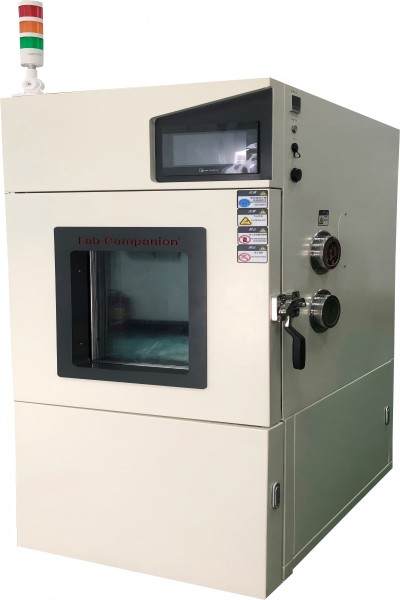
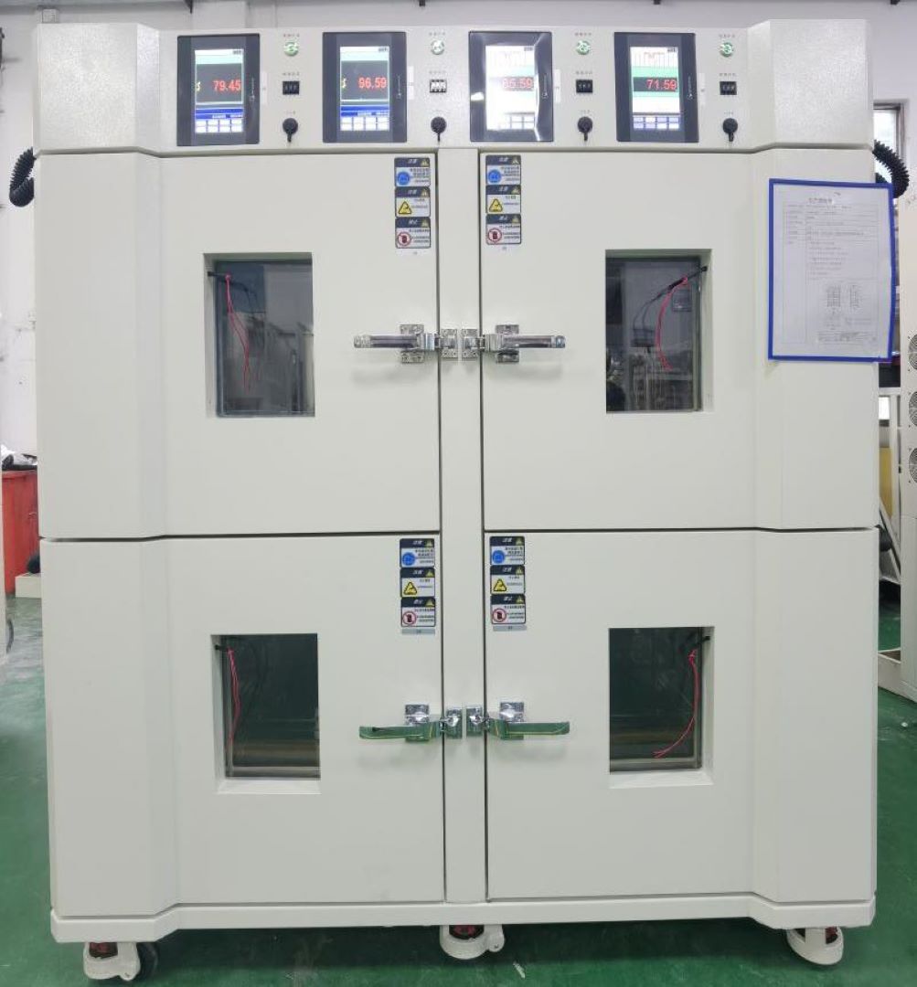
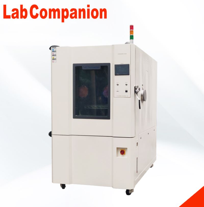
Batterie-Spezialtestkammer
Einführung in die Testkammer der Batterie-Spezialtestkammer:
Umgebungstests bei hohen und niedrigen Temperaturen (nass und heiß) für Lithium-Batteriezellen, -Module und den Test von Batteriepaketen für Elektrofahrzeuge; Es wird auch für Umgebungstests bei hohen und niedrigen Temperaturen (nass und heiß) von Lithiumbatteriezellen und -modulen im Zusammenhang mit der Energiespeicherindustrie verwendet.
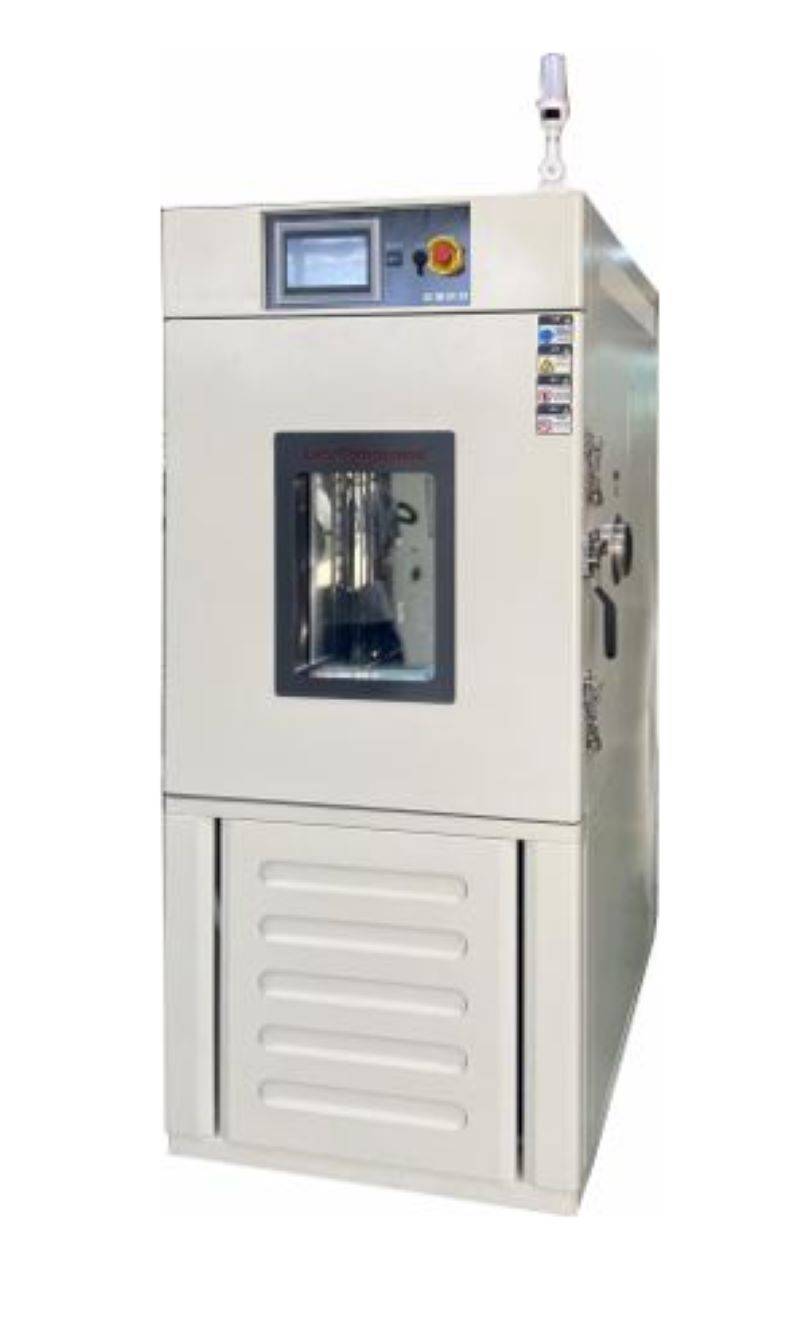
Hauptparameter der Batterie-Spezialtestkammer:
Studiogröße: 0,3 m ~ 1,5 m³ (andere Größen können angepasst werden)
Temperaturbereich: -40 ℃ ~ +150 ℃
Luftfeuchtigkeitsbereich: 20 % ~ 98 %
Heizrate: 1℃ -5 ℃/min (Der gesamte Prozess)
Abkühlrate: 1℃ -5 ℃/min (Der gesamte Prozess)
Temperaturschwankung: ±0,5
Temperaturgleichmäßigkeit: 2℃
Temperaturabweichung: ±2℃
Luftfeuchtigkeitsabweichung: +2 ~ -3 % (> 75 % rF), ± 5 % (≤ 75 % rF)
Burn-in-TestBurn-in-Test ist der Prozess, durch den ein System frühzeitig Ausfälle von Halbleiterkomponenten (Kindersterblichkeit) erkennt und so die Zuverlässigkeit einer Halbleiterkomponente erhöht. Normalerweise werden Einbrenntests an elektronischen Geräten wie Laserdioden mit einem automatischen Laserdioden-Einbrennsystem durchgeführt, das die Komponente über einen längeren Zeitraum laufen lässt, um Probleme zu erkennen.Ein Burn-in-System nutzt modernste Technologie, um die Komponente zu testen und präzise Temperaturkontrolle, Leistung und optische (falls erforderlich) Messungen bereitzustellen, um die Präzision und Zuverlässigkeit sicherzustellen, die für die Herstellung, technische Bewertung und F&E-Anwendungen erforderlich sind.Einbrenntests können durchgeführt werden, um sicherzustellen, dass ein Gerät oder System ordnungsgemäß funktioniert, bevor es das Fertigungswerk verlässt, oder um zu bestätigen, dass neue Halbleiter aus dem Forschungs- und Entwicklungslabor die vorgesehenen Betriebsanforderungen erfüllen.Das Einbrennen erfolgt am besten auf Komponentenebene, wenn die Kosten für das Testen und Ersetzen von Teilen am niedrigsten sind. Das Einbrennen einer Platine oder Baugruppe ist schwierig, da für verschiedene Komponenten unterschiedliche Grenzwerte gelten.Es ist wichtig zu beachten, dass der Burn-In-Test normalerweise dazu dient, Geräte herauszufiltern, die während der „Säuglingssterblichkeitsphase“ (Beginn der Badewannenkurve) ausfallen, und dass die „Lebensdauer“ oder Abnutzung (Ende der Badewanne) nicht berücksichtigt wird Kurve) – hier kommt die Zuverlässigkeitsprüfung ins Spiel.Verschleiß ist das natürliche Ende der Lebensdauer einer Komponente oder eines Systems im Zusammenhang mit der kontinuierlichen Nutzung aufgrund der Wechselwirkung von Materialien mit der Umwelt. Dieses Versagensregime ist für die Lebensdauer des Produkts von besonderer Bedeutung. Es ist möglich, den Verschleiß mathematisch zu beschreiben, was das Konzept der Zuverlässigkeit und damit die Vorhersage der Lebensdauer ermöglicht.Was führt dazu, dass Komponenten beim Einbrennen ausfallen?Die Hauptursache für Fehler, die während des Burn-In-Tests erkannt werden, können dielektrische Fehler, Leiterfehler, Metallisierungsfehler, Elektromigration usw. sein. Diese Fehler sind inaktiv und manifestieren sich zufällig in Geräteausfällen während des Gerätelebenszyklus. Beim Burn-In-Test belastet ein automatisches Testgerät (ATE) das Gerät, wodurch sich diese ruhenden Fehler schneller als Ausfälle manifestieren und Ausfälle während der Kindersterblichkeitsphase aussortieren.Burn-In-Tests erkennen Fehler, die im Allgemeinen auf Unvollkommenheiten in den Herstellungs- und Verpackungsprozessen zurückzuführen sind, die mit zunehmender Schaltungskomplexität und aggressiver Technologieskalierung immer häufiger auftreten.Burn-in-TestparameterDie Spezifikationen für einen Burn-In-Test variieren je nach Gerät und Teststandard (Militär- oder Telekommunikationsstandards). Es erfordert normalerweise die elektrische und thermische Prüfung eines Produkts unter Verwendung eines erwarteten elektrischen Betriebszyklus (extreme Betriebsbedingungen), typischerweise über einen Zeitraum von 48 bis 168 Stunden. Die thermische Temperatur der Einbrennprüfkammer kann zwischen 25 °C und 140 °C liegen.Das Einbrennen wird bei Produkten während ihrer Herstellung angewendet, um frühzeitig Ausfälle zu erkennen, die durch Fehler in der Herstellungspraxis verursacht werden.Burn In führt im Wesentlichen Folgendes aus:Stress + extreme Bedingungen + Zeit verlängern = Beschleunigung der „normalen/nützlichen Lebensdauer“Arten von Burn-in-TestsDynamisches Einbrennen: Das Gerät wird hohen Spannungen und extremen Temperaturen ausgesetzt und gleichzeitig verschiedenen Eingabereizen ausgesetzt.Ein Burn-in-System gibt an jedes Gerät verschiedene elektrische Reize, während das Gerät extremen Temperaturen und Spannungen ausgesetzt ist. Der Vorteil des dynamischen Einbrennens besteht darin, dass es mehr interne Schaltkreise belasten kann, wodurch zusätzliche Fehlermechanismen auftreten. Das dynamische Einbrennen ist jedoch begrenzt, da es nicht vollständig simulieren kann, was das Gerät während der tatsächlichen Verwendung erleben würde, sodass möglicherweise nicht alle Schaltungsknoten belastet werden.Statisches Einbrennen: Der Prüfling (DUT) wird über einen längeren Zeitraum einer erhöhten, konstanten Temperatur ausgesetzt.Ein Burn-In-System legt extreme Spannungen, Ströme und Temperaturen an jedes Gerät an, ohne dass das Gerät bedient oder trainiert werden muss. Die Vorteile des statischen Einbrennens liegen in den geringen Kosten und der Einfachheit.Wie wird ein Burn-In-Test durchgeführt?Das Halbleiterbauelement wird auf speziellen Burn-in-Boards (BiB) platziert, während der Test in einer speziellen Burn-in-Kammer (BIC) durchgeführt wird.Erfahren Sie mehr über Burn-in Chamber (hier klicken)
Hoch- und Niedertemperatur-Niederdruck-Testgeräte und schnelles DekompressionsgerätPrüfkammer für hohe und niedrige Temperaturen und niedrigen Druck:(1). Wichtigste technische Indikatoren1. Studiogröße: 1000T×1000B×1000H mm, die Innengröße beträgt etwa 1000L2. Außengröße: ca. 3400T×1400B×2010H mm, ohne Controller, Testloch und andere hervorstehende Teile.3. Temperaturbereich: -70℃ ~ +150℃4. Temperaturschwankung: ≤±0,5℃, Normaldruck, keine Last5. Temperaturabweichung: ±2℃, Normaldruck, keine Last6. Temperaturgleichmäßigkeit: ≤2℃, Atmosphärendruck, Leerlauf7. Heizrate: +20℃→+150℃≤60min8. Abkühlrate: +20℃→-65℃≤60min9. Luftfeuchtigkeitsbereich: Luftfeuchtigkeit 20 % ~ 98 % RH (Temperaturbereich +20℃ ~ +85℃)10. Luftfeuchtigkeitsabweichung: ≤+ 2–3 % RH (> 75 % RH), ≤ ± 5 % RH (≤ 75 % RH), unter normalen Druck- und Leerlaufbedingungen.11. Druckbereich: Normaldruck ~ 0,5 kPa12. Druckreduzierungsrate: Normaldruck ~ 1,0 kPa ≤ 30 Min13. Druckwiederherstellungsrate: ≤10,0 kPa/min14. Druckabweichung: Normaldruck ~ 40 kPa: ≤ ± 2 kPa, 40 kPa ~ 4 kPa: ≤ ± 5 % kPa, unter 4 kPa: ≤ ± 0,1 kPa15. Windgeschwindigkeit: Einstellung der Frequenzumwandlung16. Leistung: ca. 50 kW17. Lärm: ≤75 dB (A), 1 Meter von der Vorderseite der Kammer entfernt und 1,2 Meter über dem Boden.18. Gewicht: 1900 kg(2). Schnelldekompressionsgerät (optional)Um den Anforderungen einer schnellen Druckentlastung gerecht zu werden, wird eine unabhängige Schnellentlüftungskammer verarbeitet. Die Kammer zur schnellen Druckentlastung besteht aus einer Gehäusebaugruppe, einer Druckbaugruppe, einer Türbaugruppe, einer Schnittstelle und einem beweglichen Rahmen. Vor der schnellen Dekomprimierung muss der Benutzer eine externe Pipeline anschließen.1. Studiogröße: 400 mm tief x 500 mm breit x 600 mm lang; Das Innenwandmaterial wird mit 3,0 SUS304/2B verarbeitet und als Druckverstärkung wird ein 5-mm-Vierkantrohr verwendet.2. Außenmaße: 530 mm tief × 700 mm breit × 880 mm lang, das Außenwandmaterial besteht aus 1,2 mm kaltgewalztem Stahlblech, die Oberfläche ist weiß gesprüht (im Einklang mit der Farbe der Kammer);3. An der Oberseite des Behälters ist ein Drucksensoranschluss reserviert. Der Steuersensoranschluss befindet sich an der Rückseite des Containers, um die Verlegung des Schnellwechselgeräts zu erleichtern.4. Zur Erleichterung des schnellen Bewegens des Buck-Geräts. Installieren Sie vier Hubrollen unter dem Rahmen; Der bewegliche Rahmen ist aus gewöhnlichem Stahl geschweißt und auf die Oberfläche aufgesprüht.5. Schneller Dekompressionsprozess: Um die Pumpgeschwindigkeit der Kammer zur schnellen Druckentlastung zu verbessern, wird die Testkammer zunächst auf etwa 1 kPa gepumpt und das elektrische Ventil, das die Testkammerausrüstung und die Schnellreduziervorrichtung verbindet, wird geöffnet, um die Schnellreduzierfunktion zu realisieren , und das Ventil wird geschlossen, wenn es 18,8 kPa erreicht. Der konstante Druck in der Schnellentlastungskammer kann durch Hilfspumpen (Einlassventil) erreicht werden.(3). Produktimplementierungsstandards1. GB/T2423.1-2008 Test A: Niedertemperaturtest2. GB/T2423.2-2008 Test B: Niedertemperaturtest3. GB/T 2423.3-2006 Testkabine: Test bei konstanter Temperatur und Luftfeuchtigkeit4. GB/T 2423.4-2008 Test Db: Wechselnder Temperatur- und Feuchtigkeitstest5. GB/T2423.21-2008 Test M: Niederdrucktestmethode6. GB/T2423.25-2008-Test Z/AM: Umfassender Test bei niedriger Temperatur/niedrigem Druck7. GB/T2423.26-2008 Test Z/BM: umfassender Hochtemperatur-/Niederdrucktest8. Allgemeine Anforderungen für GJB150.1-20099. GJB150.2A-2009 Niederdruck-(Höhen-)Test10. GJB150.3A-2009 Hochtemperaturtest11. GJB150.4A-2009 Tieftemperaturtest12. GJB150.6-86 Temperatur-Höhen-Test13. GJB150.19-86 Temperatur-Feuchtigkeit-Höhentest14. DO16F schneller Dekompressionstest15. Technische Bedingungen der Temperatur- und Feuchtigkeitsprüfkammer GB/T 10586-200616. Technische Bedingungen der Hochtemperatur-Niederdruckprüfkammer GB/T 10590-200617. Technischer Standard für Hoch- und Niedertemperaturprüfkammern GB/T 10592-200818. GB/T 5170.1-2008 Allgemeine Regeln für Inspektionsmethoden von Umwelttestgeräten für die Elektro- und Elektronikindustrie19. GB/T 5170.2-2008 Elektrische und elektronische Produkte, Umweltprüfgeräte, Prüfverfahren, Temperatur- und Feuchtigkeitsprüfgeräte20. GB/T 5170.5-2008 Elektrische und elektronische Produkte, Umweltprüfgeräte, Prüfverfahren, Temperatur- und FeuchtigkeitsprüfgeräteGB/T 5170.10-2008 Prüfgeräte für Umwelttests für elektrische und elektronische Produkte, Prüfverfahren für Hochtemperatur- und Niederdruckprüfgeräte
Einbrennplatine für ZuverlässigkeitstestsHalbleitergeräte, die frühe Ausfälle während der „Kindersterblichkeitsphase“ testen und aussortieren, werden auf einer Platine namens „Burn-in Board“ untergebracht. Auf einer Einbrennplatine gibt es mehrere Buchsen für die Platzierung des Halbleiterbauelements (z. B. Laserdiode oder Fotodiode). Die Anzahl der Geräte, die auf einer Platine platziert werden, kann von kleinen Chargen von 64 bis zu über 1000 Geräten gleichzeitig reichen.Diese Einbrennplatten werden dann in den Einbrennofen eingesetzt, der von einem ATE (Automatic Test Equipment) gesteuert werden kann, das die erforderlichen Spannungen an die Proben liefert und gleichzeitig die gewünschte Ofentemperatur aufrechterhält. Die angelegte elektrische Vorspannung kann entweder statisch oder dynamisch sein.Normalerweise werden die Halbleiterkomponenten (z. B. Laserdioden) über das hinaus beansprucht, was sie im normalen Gebrauch aushalten müssen. Dadurch wird sichergestellt, dass der Hersteller sicher sein kann, dass er über ein robustes Laserdioden- oder Fotodiodengerät verfügt und dass die Komponente Zuverlässigkeits- und Qualifikationsstandards erfüllen kann. Materialoptionen für Einbrennplatten:IS410IS410 ist ein Hochleistungs-FR-4-Epoxidlaminat- und Prepreg-System, das entwickelt wurde, um den Anforderungen der Leiterplattenindustrie nach höherer Zuverlässigkeit und dem Trend zur Verwendung von bleifreiem Lot gerecht zu werden.370 Stunden370HR-Laminate und Prepregs werden unter Verwendung eines patentierten, hochleistungsfähigen multifunktionalen Epoxidharzsystems FR-4 mit 180 °C Tg hergestellt, das für mehrschichtige Leiterplattenanwendungen (PWB) entwickelt wurde, bei denen maximale thermische Leistung und Zuverlässigkeit erforderlich sind.BT EpoxidharzBT-Epoxidharz wird aufgrund seiner hervorragenden thermischen, mechanischen und elektrischen Eigenschaften häufig ausgewählt. Dieses Laminat ist für die bleifreie Leiterplattenbestückung geeignet. Es wird hauptsächlich für Mehrschichtplatinenanwendungen verwendet. Es zeichnet sich durch hervorragende Elektromigration, Isolationsbeständigkeit und hohe Wärmebeständigkeit aus. Es behält auch die Haftfestigkeit bei hohen Temperaturen bei.PolymidBT-Epoxidharz wird aufgrund seiner hervorragenden thermischen, mechanischen und elektrischen Eigenschaften häufig ausgewählt. Dieses Laminat ist für die bleifreie Leiterplattenbestückung geeignet. Es wird hauptsächlich für Mehrschichtplatinenanwendungen verwendet. Es zeichnet sich durch hervorragende Elektromigration, Isolationsbeständigkeit und hohe Wärmebeständigkeit aus. Es behält auch die Haftfestigkeit bei hohen Temperaturen bei.Nelco 4000-13Die Nelco® N4000-13-Serie ist ein verbessertes Epoxidharzsystem, das sowohl hervorragende thermische Eigenschaften als auch eine hohe Signalgeschwindigkeit und einen geringen Signalverlust bietet. N4000-13 SI® eignet sich hervorragend für Anwendungen, die optimale Signalintegrität und präzise Impedanzkontrolle erfordern und gleichzeitig eine hohe Zuverlässigkeit durch CAF 2 und thermischen Widerstand gewährleisten. Dicke der Einbrennplatte:0,062 Zoll – 0,125 Zoll (1,57 mm – 3,17 mm) Anwendungen für Einbrennplatinen:Während des Einbrennvorgangs herrschen extreme Temperaturen, die oft zwischen 125 °C und 250 °C oder sogar 300 °C liegen. Daher müssen die verwendeten Materialien äußerst langlebig sein. IS410 wird für Einbrennplatinenanwendungen bis 155 °C verwendet und typischerweise ein Polyimid für Anwendungen bis 250 °C. Einbrennplatinen können unter Umwelttestbedingungen verwendet werden, wie zum Beispiel:HAST (Highly Accelerated Temperature and Humidity Stress)LTOL (Low Temperature Operating Life)HTOL (Hochtemperatur-Betriebsdauer) Anforderungen an das Design der Einbrennplatine:Eine der wichtigsten Überlegungen ist die Auswahl der größtmöglichen Zuverlässigkeit und Qualität für das Burn-in-Board und den Testsockel. Sie möchten nicht, dass Ihr Burn-in-Board oder -Sockel vor dem zu testenden Gerät ausfällt. Daher sollten alle aktiven/passiven Komponenten und Anschlüsse den Hochtemperaturanforderungen entsprechen und alle Materialien und Komponenten sollten den Hochtemperatur- und Alterungsanforderungen genügen.
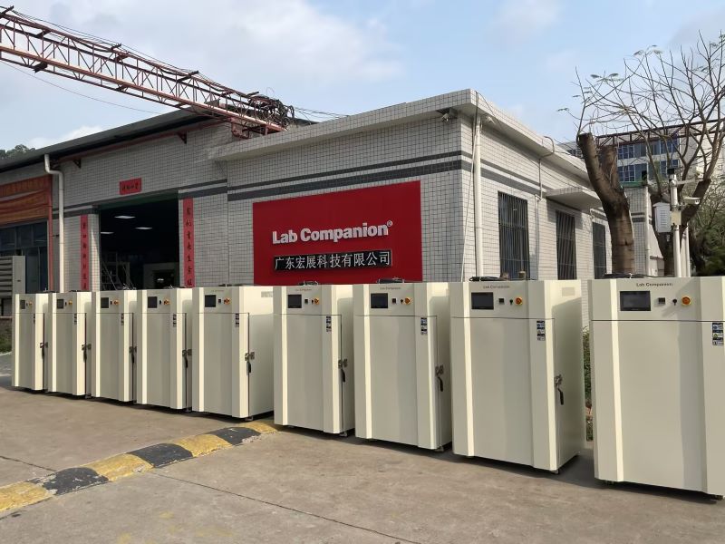
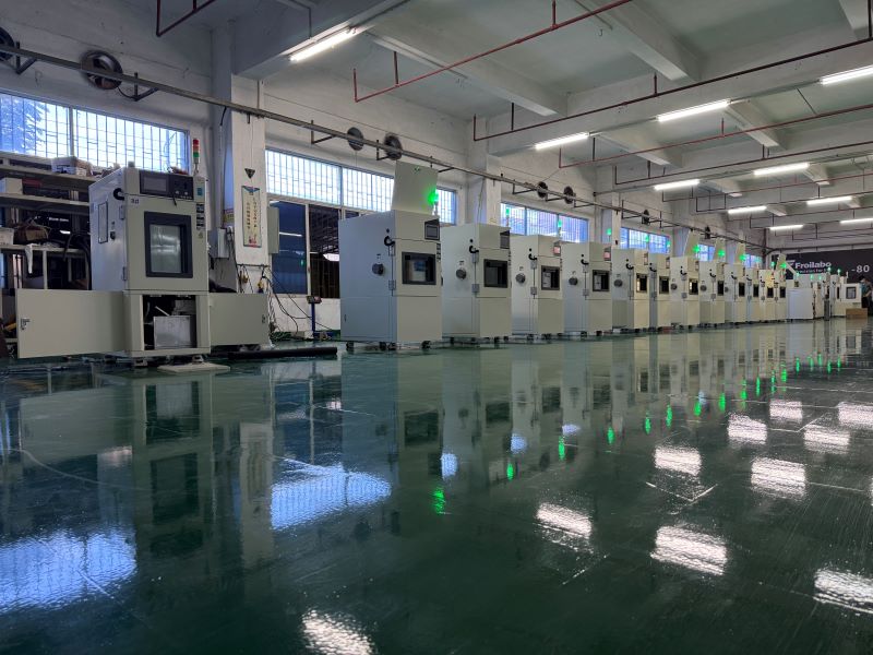
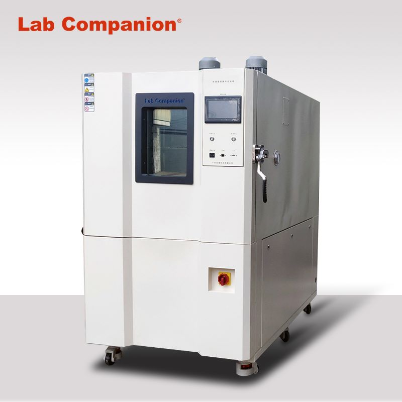
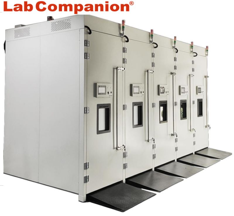
Was sind Umwelttests?Die elektronischen Geräte und Industrieprodukte, auf die wir uns täglich verlassen, werden auf vielfältige Weise von der Umwelt beeinflusst, darunter Temperatur, Luftfeuchtigkeit, Druck, Licht, elektromagnetische Wellen und Vibrationen. Umwelttests analysieren und bewerten die Auswirkungen dieser Umweltfaktoren auf das Produkt, um dessen Haltbarkeit und Zuverlässigkeit zu bestimmen.Guangdong Lab Companion LTD., verfügt über ein Grundkapital von 10 Millionen Yuan und 3 F&E-Produktionsstätten in Dongguan, Kunshan und Chongqing. Lab Companion ist seit 19 Jahren auf Hoch- und Tieftemperatur-Testgerätetechnologie spezialisiert und arbeitet nach den vier Systemen ISO9001, ISO14001, ISO 45001, ISO27001 und richtet Vertriebs- und Wartungsservicezentren in Shanghai, Wuhan, Chengdu, Chongqing, Xi'an und anderen ein Hongkong. Wir arbeiten eng mit der International Organization of Legal Metrology, der Chinese Academy of Sciences, State Grid, China Southern Power Grid, der Tsinghua University, der Peking University, der Hong Kong University of Science and Technology und anderen Forschungseinrichtungen zusammen.Zu den Hauptprodukten von Lab Companion gehören: Prüfkammer für hohe und niedrige Temperaturen, Testkammer für konstante Temperatur und Luftfeuchtigkeit, Testkammer für schnelle Temperaturwechsel, Thermoschock-Testkammer, Testkammer für hohe und niedrige Temperaturen und niedrigen Druck, Vibration der Gesamtkammer, Industrieofen, Vakuumofen, Stickstoffofen usw., die qualitativ hochwertige Experimente ermöglichen Ausrüstung für Universitäten, Forschungsinstitute, medizinische Gesundheit, Inspektion und Quarantäne, Umweltüberwachung, Lebensmittel und Medikamente, Automobilherstellung, Petrochemie, Gummi- und Kunststoffprodukte, IC-Halbleiter, IT-Herstellung und andere Bereiche.
Vibrationsüberprüfung der Funktionalität (VVF)Durch die während des Transports erzeugten Vibrationen sind Frachtkartons anfällig für komplexe dynamische Drücke und die erzeugte Resonanzreaktion ist heftig, was zu Verpackungs- oder Produktfehlern führen kann. Durch die Ermittlung der kritischen Frequenz und der Art des Drucks auf die Verpackung wird dieser Fehler minimiert. Bei der Vibrationsprüfung handelt es sich um die Beurteilung der Vibrationsfestigkeit von Bauteilen, Bauteilen und kompletten Maschinen in der zu erwartenden Transport-, Installations- und Einsatzumgebung.Gängige Vibrationsmodi können in Sinusvibrationen und Zufallsvibrationen unterteilt werden. Sinusvibration ist eine im Labor häufig verwendete Testmethode, die hauptsächlich die durch Rotation, Pulsation und Oszillation erzeugte Vibration sowie die Resonanzfrequenzanalyse und die Überprüfung des Resonanzpunktaufenthalts der Produktstruktur simuliert. Sie ist in Wobbelfrequenzvibrationen und Festfrequenzvibrationen unterteilt und ihre Schwere hängt vom Frequenzbereich, dem Amplitudenwert und der Testdauer ab. Zufällige Vibrationen werden verwendet, um die gesamte strukturelle seismische Festigkeitsbewertung des Produkts und der Versandumgebung im verpackten Zustand zu simulieren, wobei der Schweregrad vom Frequenzbereich, dem GRMS, der Testdauer und der axialen Ausrichtung abhängt.Vibrationen können nicht nur die Lampenkomponenten lockern, so dass die interne relative Verschiebung zu Entschweißen, schlechtem Kontakt und schlechter Arbeitsleistung führt, sondern auch dazu führen, dass die Komponenten Lärm, Verschleiß, physisches Versagen und sogar Komponentenermüdung verursachen.Zu diesem Zweck hat Lab Companion einen professionellen „LED-Lampen-Vibrationstest“ ins Leben gerufen, um die Vibrationen oder mechanischen Stöße zu simulieren, die in der tatsächlichen Transport-, Installations- und Nutzungsumgebung der Lampe auftreten können, und um die Vibrationsfestigkeit und Stabilität der LED-Lampe zu bewerten der zugehörigen Leistungsindikatoren und finden Sie das schwache Glied, das zu Schäden oder Ausfällen führen kann. Verbessern Sie die Gesamtzuverlässigkeit von LED-Produkten und verbessern Sie den Ausfallstatus der Branche aufgrund von Transport oder anderen mechanischen Stößen.Servicekunden: LED-Beleuchtungsfabrik, Beleuchtungsagenten, Beleuchtungshändler, DekorationsunternehmenTestmethode:1, die LED-Lampen-Probenverpackung auf dem Vibrationsprüfstand platziert;2, die Vibrationsgeschwindigkeit des Vibrationstesters ist auf 300 U/min eingestellt, die Amplitude ist auf 2,54 cm eingestellt, starten Sie den Vibrationsmesser;3, die Lampe gemäß der oben genannten Methode in den drei Richtungen oben und unten, links und rechts, vorne und hinten jeweils 30 Minuten lang testen.Ergebnisauswertung: Nach dem Vibrationstest können an der Lampe keine herunterfallenden Teile, strukturelle Schäden, Beleuchtung und andere ungewöhnliche Phänomene auftreten.
Double 85 Zuverlässigkeits-Umwelttest bei konstanter Temperatur und Luftfeuchtigkeit (THB)Zuerst Hochtemperatur- und FeuchtigkeitstestWHTOL (Wet High Temperature Operating Life) ist ein üblicher Umweltbelastungsbeschleunigungstest, normalerweise 85 °C und 85 % relative Luftfeuchtigkeit, der im Allgemeinen gemäß der Norm IEC 60068-2-67-2019 durchgeführt wird. Die Testbedingungen sind in der Tabelle dargestellt.Zweitens das Testprinzip„Doppelter 85-Test“ ist einer der Zuverlässigkeits-Umwelttests, der hauptsächlich für Boxen mit konstanter Temperatur und Luftfeuchtigkeit verwendet wird, d Alterung des Testprodukts. Obwohl der Testprozess einfach ist, ist der Test eine wichtige Methode zur Bewertung vieler Eigenschaften des Testprodukts und hat sich daher in verschiedenen Branchen zu einer unverzichtbaren Zuverlässigkeits- und Umwelttestbedingung entwickelt.Vergleichen Sie nach der Alterung des Produkts bei 85 °C/85 % relativer Luftfeuchtigkeit die Leistungsänderungen des Produkts vor und nach der Alterung, z. B. die photoelektrischen Leistungsparameter der Lampe, die mechanischen Eigenschaften des Materials, den Gelbindex usw. Je kleiner der Unterschied, desto besser, um die Hitze- und Feuchtigkeitsbeständigkeit des Produkts zu testen.Beim Betrieb in einer Umgebung mit kontinuierlich hohen Temperaturen kann es zu einem thermischen Ausfall des Produkts kommen, und einige feuchtigkeitsempfindliche Geräte versagen in einer Umgebung mit hoher Luftfeuchtigkeit. Der Dual-85-Test kann die thermische Belastung testen, die das Produkt bei hoher Luftfeuchtigkeit erzeugt, und seine Fähigkeit, einem langfristigen Eindringen von Feuchtigkeit zu widerstehen. Beispielsweise ist der häufige Ausfall verschiedener Produkte in der feuchten Wetterperiode im Süden hauptsächlich auf die schlechte Temperatur- und Feuchtigkeitsbeständigkeit der Produkte zurückzuführen.3. Experimentelle FaktorenIn der LED-Beleuchtungsindustrie haben viele Hersteller die Double-85-Testergebnisse als wichtiges Mittel zur Beurteilung der Qualität von Lampen genutzt. Verschiedene mögliche Gründe, warum LED-Lampen den Dual-85-Test nicht bestehen, sind:1. Lampenstromversorgung: schlechte Hitzebeständigkeit des Gehäuses, Gefahr eines Kurzschlusses im Stromkreis, Ausfall des Schutzmechanismus usw.2. Lampenstruktur: unangemessenes Design des Wärmeableitungskörpers, Installationsprobleme, Materialien sind nicht beständig gegen hohe Temperaturen.3. Lampenlichtquelle: schlechte Feuchtigkeitsbeständigkeit, Alterung des Verpackungsklebers, hohe Temperaturbeständigkeit.Wenn Sie auf eine besondere Einsatzumgebung stoßen, z. B. wenn die Temperatur in der Arbeitsumgebung hoch ist, müssen Sie die Beständigkeit gegen hohe und niedrige Temperaturen testen. Die Testmethode kann sich auf das Testprojekt für hohe und niedrige Temperaturen beziehen.4. Kunden bedienen01. KundengruppeLED-Beleuchtungsfabrik, LED-Kraftwerk, LED-Verpackungsfabrik02. NachweismittelPrüfkammer für konstante Temperatur und Luftfeuchtigkeit03. ReferenzstandardsTests bei konstanter Temperatur und Luftfeuchtigkeit für elektrische und elektronische Produkte – Umweltprüfungen – Teil 2: Testmethoden – Testkabine: Test bei konstanter Temperatur und Luftfeuchtigkeit GB/T 2423.3-2006.04. Serviceinhalte4.1 Beachten Sie die Norm, führen Sie einen doppelten 85-Test für das Produkt durch und stellen Sie den Testergebnisbericht des Dritten bereit.4.2 Bereitstellung der Analyse und des Verbesserungsplans des Produkts durch den Double 85-Test.
Lab Companion-Schnelltemperaturwechsel-TestkammerEinführung von Lab CompanionMit über 20 Jahren Erfahrung, Laborbegleiter ist ein erstklassiger Hersteller von Klimakammern und ein versierter Lieferant schlüsselfertiger Testsysteme und -geräte. Alle unsere Kammern bauen auf dem Ruf von Lab Companion für lange Lebensdauer und außergewöhnliche Zuverlässigkeit auf. Lab Companion hat im Hinblick auf Design, Herstellung und Service ein Qualitätsmanagementsystem eingerichtet, das der internationalen Qualitätssystemnorm ISO 9001:2008 entspricht. Das Gerätekalibrierungsprogramm von Lab Companion ist von A2LA nach dem internationalen Standard ISO 17025 und dem amerikanischen Nationalstandard ANSI/NCSL-Z-540-1 akkreditiert. A2LA ist Vollmitglied und Unterzeichner der International Laboratory Accreditation Cooperation (ILAC), der Asia Pacific Laboratory Accreditation (APLAC) und der European Cooperation for Accreditation (EA). Die Umwelttestkammern der SE-Serie von Lab Companion bieten ein deutlich verbessertes Luftstromsystem, das bessere Gradienten und verbesserte Änderungsraten der Produkttemperatur bietet. Diese Kammern nutzen den Flaggschiff-8800-Programmierer/Controller von Thermotron mit einem hochauflösenden 12,1-Zoll-Flachbildschirm mit Touchscreen-Benutzeroberfläche, erweiterten Funktionen zur grafischen Darstellung, Datenprotokollierung, Bearbeitung, Zugriff auf die Bildschirmhilfe und langfristiger Datenspeicherung auf der Festplatte.Wir bieten nicht nur Produkte von höchster Qualität, sondern bieten auch fortlaufenden Support, der dafür sorgt, dass Sie lange nach dem ersten Verkauf einsatzbereit bleiben. Wir bieten einen direkten Werksservice vor Ort mit einem umfangreichen Lagerbestand der Teile, die Sie möglicherweise benötigen. LeistungTemperaturbereich: -70°C bis +180°CLeistung: Bei einer Aluminiumlast von 23 kg (IEC60068-3-5) beträgt die Anstiegsrate von +85 °C auf -40 °C 15 °C/Minute; Die Abkühlgeschwindigkeit von -40°C bis +85°C beträgt ebenfalls 15℃/min.Temperaturregelung: ± 1 °C Trockenkugeltemperaturen vom Kontrollpunkt nach Stabilisierung am KontrollsensorDie Leistung basiert auf einer Umgebungstemperatur von 75 °F (23,9 °C) und 50 % relativer LuftfeuchtigkeitKühl-/Heizleistung basierend auf der Messung am Regelfühler im ZuluftstromKonstruktionInnereNichtmagnetischer Edelstahl der Serie 300 mit hohem NickelgehaltHeliarc-geschweißte Innennähte sorgen für eine hermetische Abdichtung des LinersEcken und Nähte sind so gestaltet, dass sie sich bei extremen Temperaturen ausdehnen und zusammenziehen könnenDer Kondensatablauf befindet sich im Linerboden und unter dem KlimatisierungsplenumDer Kammerboden ist vollständig verschweißt„Ultra-Lite“-Glasfaserisolierung, die sich nicht absetztEin verstellbares Innenregal aus Edelstahl ist StandardAußenGesenkgeformtes, behandeltes StahlblechZugangsabdeckungen aus Metall ermöglichen das einfache Öffnen der Türen zu elektrischen KomponentenWasserbasierter, lufttrocknender Finish-Lack, der auf eine gereinigte und grundierte Oberfläche gesprüht wirdLeicht abhebbare Zugangstüren mit Scharnieren für die Wartung des KühlsystemsEine Zugangsöffnung mit 12,5 cm Durchmesser, Innenschweißung und abnehmbarem Isolierstopfen, montiert im rechten Seitenwandzubehör an der Flügeltür für einfachen ZugangMerkmaleChamber Operation zeigt hilfreiche Laufzeitinformationen übersichtlich anGraphing Screen bietet erweiterte Funktionen, verbesserte Programmierung und BerichterstellungDer Systemstatus zeigt wichtige Parameter des Kühlsystems anProgram Entry erleichtert das Laden, Anzeigen und Bearbeiten von ProfilenEinrichtungs-Schnellassistenten erleichtern die ProfileingabePopup-Kühldiagramme als praktische ReferenzTherm-Alarm® bietet Über- und UntertemperaturalarmschutzDer Aktivitätsprotokollbildschirm bietet einen umfassenden GeräteverlaufDer Webserver ermöglicht den Internetzugriff auf Geräte über EthernetDie benutzerfreundliche Popup-Tastatur ermöglicht eine schnelle und einfache DateneingabeBeinhaltet:- Vier USB-Anschlüsse – zwei externe und zwei interne- Ethernet- RS-232Technische Spezifikationen1–4 unabhängig programmierbare KanäleMessgenauigkeit: typisch 0,25 % der SpanneWählbare Temperaturskala in °C oder °F12,1 Zoll (30 cm) Farb-Flachbildschirm-Touchscreen-DisplayAuflösung: 0,1 °C, 0,1 % RH, 0,01 für andere lineare AnwendungenEchtzeituhr inklusiveAbtastrate: Prozessvariable, die alle 0,1 Sekunden abgetastet wirdProportionalband: Programmierbar 1,0° bis 300°Steuerungsmethode: DigitalIntervalle: UnbegrenztIntervallauflösung: 1 Sek. bis 99 Std., 59 Min. mit 1-Sekunden-Auflösung- RS-232- 10+ Jahre Datenspeicherung- Produkttemperaturkontrolle- Ereignis-RelaisplatineBetriebsmodi: Automatisch oder manuellProgrammspeicher: UnbegrenztProgrammschleifen:- Bis zu 64 Schleifen pro ProgrammSchleifen können im Programm bis zu 9.999 Mal wiederholt werden- Bis zu 64 verschachtelte Schleifen pro Stück sind zulässig
Wenn Sie an unseren Produkten interessiert sind und weitere Einzelheiten erfahren möchten, hinterlassen Sie bitte hier eine Nachricht. Wir werden Ihnen so schnell wie möglich antworten.


 Ein Angebot bekommen
 IPv6-Netzwerk unterstützt