Lab Companion TC Series Rapid Temperature Change Test Chamber: Technical Core & Performance Advantages | Made in China
Jul 15, 2026
1. Core Value of Rapid Temperature Cycling Testing in Reliability Validation
1.1 Significance of Environmental Reliability Testing in Global Manufacturing
In modern global industrial manufacturing, a product’s environmental adaptability and operational reliability are core determinants of its service life and market competitiveness. All mainstream industrial products, including consumer electronics, automotive components, semiconductors, and aerospace equipment, must undergo rigorous environmental reliability validation before global market launch.
As a critical piece of environmental simulation testing equipment, the rapid temperature change test chamber replicates extreme and fluctuating temperature conditions encountered during product storage, transportation, and real-world service. It effectively evaluates product structural integrity and functional stability under rapid thermal variation stress.
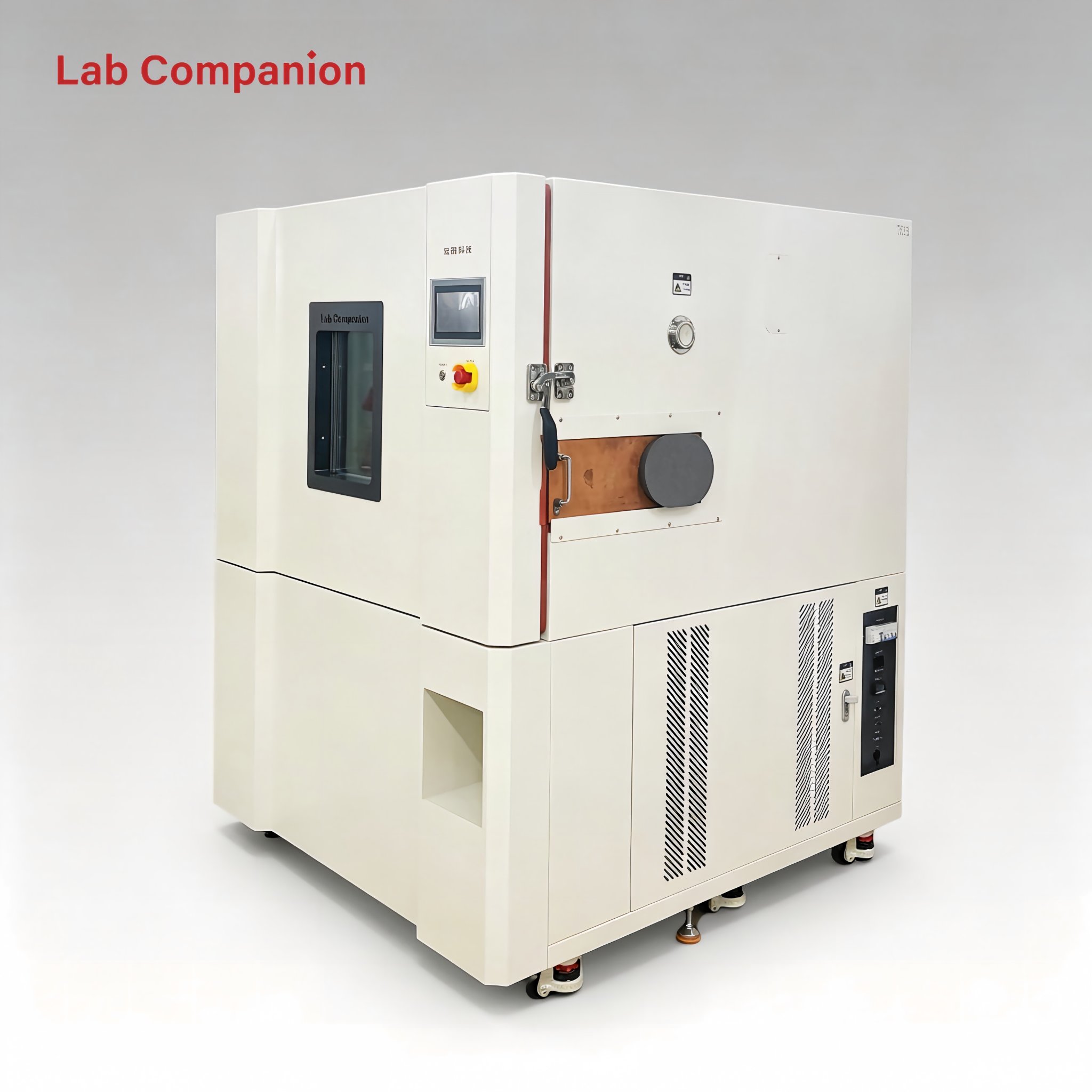
Lab Companion is a premium environmental test equipment brand rooted inChina’s advanced intelligent manufacturing industry. With over 20 years of specialized focus on reliability testing equipment R&D and production, our TC Series rapid temperature change test chamber has become a trusted solution for global enterprises. Featuring precise temperature regulation, wide temperature coverage, and multi-speed thermal cycling options, it is widely applied in Environmental Stress Screening (ESS) and high-standard product reliability verification worldwide.
1.2 Core Technical Challenges of Rapid Temperature Change Testing
Compared with conventional constant temperature testing, rapid temperature cycling poses stricter technical requirements for test equipment. It demands ultra-fast response from heating and refrigeration systems to achieve drastic temperature shifts within a short period. Meanwhile, consistent temperature field uniformity and high control accuracy must be maintained throughout rapid thermal changes to prevent distorted test data and ensure valid, repeatable results.
Targeting these universal industry technical pain points, Lab Companion (Made in China) has completed systematic optimization for the TC Series. With self-developed refrigeration architecture, optimized air duct structure, and intelligent adaptive control algorithms, our equipment delivers stable, high-precision performance even under high-speed temperature cycling conditions, solving the core industry challenge of balancing fast ramp rates and uniform temperature control.
2. In-Depth Interpretation of Core Technical Parameters
2.1 Ultra-Wide Temperature Range for Full-Condition Coverage
Temperature coverage is the foundational indicator of environmental test chamber performance. The standard model of Lab Companion TC Series delivers a wide temperature range of -70℃ to +150℃, covering extreme low-temperature cold environments and high-temperature industrial operating conditions. It fully meets the full-temperature-cycle reliability testing requirements for most commercial and industrial products across global industries.
To accommodate customized demands for high-end fields such as semiconductors and aerospace, Lab Companion supports exclusive temperature range extension solutions. As a professional Chinese manufacturing brand, we tailor ultra-low and ultra-high temperature testing configurations to match stringent international industry standards and special client testing scenarios.
2.2 Multi-Grade Temperature Ramp Rates for Flexible Testing
The temperature ramp rate defines thermal stress intensity and overall testing efficiency, serving as the core performance metric of rapid temperature change chambers. The Lab Companion TC Series provides five optional ramp rates: 5℃/min, 10℃/min, 15℃/min, 20℃/min, and 25℃/min, supporting both linear and non-linear temperature variation modes. Global users can flexibly select parameters based on international test specifications and product characteristics.
• 5℃/min: Suitable for conventional thermal cycling tests, simulating gradual natural ambient temperature changes for general product reliability validation.
• 10℃/min: Ideal for standard environmental stress screening, achieving an optimal balance of testing efficiency and energy consumption.
• 15℃/min: Applies medium-intensity thermal stress to accelerate the exposure of latent defects in precision electronic components.
• 20℃/min: Enables high-efficiency stress screening, significantly shortening test cycles and accelerating customer R&D iteration and time-to-market.
• 25℃/min: Supports extreme thermal stress testing to meet the rigorous verification standards of high-end semiconductor, aerospace, and precision industrial products.
Taking the typical semiconductor thermal cycle test (-40℃ to +150℃) as an example, the 20℃/min ramp rate drastically reduces single-cycle testing duration, improving laboratory operational efficiency and helping global clients accelerate product launch progress.
2.3 High-Precision Temperature Control & Uniformity
Maintaining precise and stable temperature control during rapid thermal cycling is the key benchmark of premium equipment quality. The Lab Companion TC Series achieves industry-leading precision performance: Temperature Deviation: ±1.5℃, Temperature Fluctuation: ±0.1~±0.5℃, Temperature Uniformity: ≤±2℃. This ensures consistent thermal conditions across the entire test workspace, guaranteeing accurate and reproducible test data.
This superior precision stems from Lab Companion’s accumulated Chinese manufacturing technology advantages. The optimized closed-loop air duct structure realizes uniform internal air circulation without temperature dead zones. Equipped with high-precision sensors and self-adaptive intelligent control algorithms, the system achieves real-time dynamic temperature calibration and precise regulation throughout all test stages.
3. Analysis of Core Technical Systems
3.1 Dual-Stage Cascade Refrigeration System
A high-performance refrigeration system determines the equipment’s low-temperature capacity and cooling response speed. Developed and optimized based on Chinese advanced industrial refrigeration technology, the Lab Companion TC Series adopts a high-efficiency dual-stage cascade refrigeration system.
The system consists of independent high-stage and low-stage refrigeration loops connected via an evaporative condenser for efficient heat exchange. The high-stage loop provides stable condensing load for the low-stage system, while the low-stage loop directly delivers precise cooling capacity to the test chamber. This cascade design effectively reduces compressor pressure ratio, boosts overall refrigeration efficiency, and supports stable operation at -70℃ ultra-low temperature.
All core refrigeration components adopt globally renowned high-quality accessories. Supported by intelligent energy regulation technology, the system automatically matches power output according to different temperature ranges and ramp speeds, ensuring long-term stable operation and low energy consumption for global users.
3.2 Q8 Intelligent Control System
Lab Companion equips the TC Series with the self-developed Q8 intelligent control system, integrating AI fuzzy logic and self-tuning PID technology to realize adaptive and high-precision temperature regulation.
Featuring a large full-color touchscreen with English-Chinese bilingual switching, the system delivers an intuitive and user-friendly operation interface for global users. It comes with built-in universal international test program templates and supports custom multi-segment program editing and cyclic operation, fully adapting to complex global testing process requirements.
In terms of data management, the Q8 system supports real-time data display, automatic storage, one-click export, and standardized test report generation for complete data traceability and analysis. It also integrates remote monitoring functions, allowing users to view equipment operating status and test progress remotely, realizing intelligent and unmanned laboratory management.
3.3 Multi-Layer Comprehensive Safety Protection Mechanism
Safety is the primary premise for long-term stable equipment operation. Adhering to strict Chinese industrial safety standards and international certification specifications, the Lab Companion TC Series is equipped with a full set of multi-dimensional safety protection mechanisms to safeguard equipment, samples, and operators.
Temperature safety protection: An independent over-temperature protection device automatically cuts off heating and refrigeration power and triggers audible and visual alarms once the temperature exceeds the safe threshold, preventing sample damage and equipment failure caused by temperature runaway.
System operation protection: Built-in compressor overload protection, high/low pressure protection, fan fault alarm, and leakage protection realize full-time monitoring of refrigeration and electrical systems to eliminate potential operating risks.
Operational safety protection: The door safety interlock automatically pauses ongoing tests when the chamber door is opened, protecting operators from extreme temperature injuries.
4. Product Portfolio & Global Application Scenarios
4.1 Full-Size Product Matrix & Customization Capability
As a reliable Chinese intelligent manufacturing brand, Lab Companion builds a complete product matrix covering diverse testing scenarios, ranging from 50L desktop compact chambers to 20m³ large walk-in thermal rooms, meeting the testing demands of different sample sizes and batch volumes.
Desktop Series (50L~150L): Compact footprint and flexible operation, ideal for laboratory R&D and small component testing.
Standard Series (225L~1000L): Widely applicable to module and small finished product testing, serving as the most mainstream specification for global industrial laboratories.
Walk-In Series (2m³~20m³): Customizable large-space chambers for whole-machine, large-component, and multi-batch simultaneous testing.
Meanwhile, Lab Companion provides professional non-standard customization services, including special temperature ranges, ultra-fast ramp rates, multi-zone temperature control, and explosion-proof designs, to deliver personalized testing solutions for global high-end clients.
4.2 Multi-Industry Global Application
Benefiting from reliable quality and international standard compliance, the Lab Companion TC Series is widely exported and applied in semiconductor, automotive electronics, new energy, aerospace, communication, and medical industries worldwide.
Semiconductor & Electronic Industry: Conducts environmental stress screening for chips, PCBs, and precision electronic components, accelerating the exposure of manufacturing defects and improving product reliability.
Automotive Electronic Industry: Meets global automotive grade testing standards to verify the operational stability of automotive sensors, control modules, and in-vehicle systems under extreme temperature fluctuation.
New Energy Industry: Performs thermal cycling tests for battery modules and BMS systems to evaluate the environmental adaptability and service life of new energy products.
Lab Companion consistently delivers high-qualityMade in China environmental test equipment to support high-standard reliability verification for global high-end manufacturing industries.
5. Brand Strength & Global Service System
5.1 Independent R&D Strength & Strict Quality Control
Lab Companion is backed by a national high-tech enterprise in China, specializing in the R&D and manufacturing of environmental test equipment. With over two decades of industry experience, we own independent intellectual property rights and core technologies in refrigeration systems, structural design, and intelligent control algorithms.
We implement a strict full-process quality management system certified by ISO9001, ISO14001, ISO45001, and ISO27001. Every piece of equipment undergoes rigorous factory performance calibration and aging testing, ensuring stable and consistent quality for all global end users.
5.2 Global Online Technical Support & Full-Lifecycle Service
Rooted in China’s advanced manufacturing base, Lab Companion focuses on global market layout and international user service. To adapt to overseas user scenarios, we provide full-lifecycle online technical support for all global clients (no on-site door-to-door service for overseas regions).
Our professional international service team provides one-stop remote support covering pre-sales solution consultation, model selection guidance, equipment operation training, real-time online debugging, fault diagnosis, and regular technical maintenance guidance. We ensure 24-hour rapid global response, efficiently solving equipment operation problems remotely and guaranteeing continuous and stable laboratory testing progress for overseas users.
Lab Companion — Your Reliable Made-in-China Partner for Global Environmental Reliability Testing. We will continue to empower global manufacturing quality upgrading through technological innovation and professional cross-border services.
Mehr lesen


 Ein Angebot bekommen
 IPv6-Netzwerk unterstützt