As power consumption of AI servers keeps rising, air cooling is gradually giving way to liquid cooling. Cold plates are attached directly to chips, pipelines run through the rack, and heat is carried away by circulating coolant. While cooling efficiency improves, test complexity increases accordingly. During each thermal cycle of the complete system, thermal expansion and contraction occur not only in air, but also in cold plates, pipelines, fittings and solder joints, where different materials undergo thermally induced stress. Thermal cycling validation for liquid-cooled servers focuses on the consistency of the system’s thermal structure, rather than whether a single chip can power on.
1. Thermal Risks of Liquid-Cooled Servers
1.1 Thermal Stress on Cold Plates and Pipelines
Cold plates are commonly made of copper or aluminum, while pipelines and fittings are composite assemblies combining rubber, engineering plastics and metals. Subjected to temperature changes, these materials expand and contract at different rates. Shear stress builds up at joints and bending stress accumulates along bent pipe sections. After repeated cycles, joint leakage and pipeline fatigue usually occur earlier than electrical failures — defects that can hardly be detected through ambient burn-in tests.
1.2 Thermo-Mechanical Fatigue of Solder Joints and Packages
Chip packages are multi-layer structures composed of silicon, solder, substrate and PCB. Temperature cycling creates differential expansion across these layers, imposing cyclic shear strain on solder joints and initiating microcracks. As cracks propagate, contact resistance rises, driving local power dissipation and temperature higher and forming a self-reinforcing thermal degradation loop.
1.3 Coolant Property Variation at Low Temperatures
Coolant viscosity increases sharply as temperature drops, reducing fluidity at low temperatures. Pumping resistance rises and flow rate decreases. Insufficient flow leads to localized hot spots on chips. Observed performance fluctuations during testing are sometimes caused by shifting cooling conditions due to changing coolant properties, instead of chip defects.
2. Key Requirements for System-Level Thermal Cycling Testing
2.1 Large Chamber Volume and High Load Capacity
A single server unit can weigh dozens of kilograms, and rack-mounted samples are even heavier. The chamber must provide ample space for the unit, wiring and tubing. The sample shelf and base structure shall be engineered for full-load weight. Unsecured samples may shift during cycling, loosening connections and corrupting monitoring data, rendering test results invalid.
2.2 Powered-On Monitoring and Feedthrough Ports
Tests must run with the server powered on to capture dynamic performance drift. The chamber shall be equipped with feedthrough ports to route power, network and monitoring signals outside. Poorly sealed or insulated ports become thermal leakage points. Cables tend to stiffen and embrittle at low temperatures and may crack under repeated flexing, so routing must be planned in advance.
2.3 Controlled Ramp Rate and Temperature Uniformity
Complete servers have high thermal mass. Ramp rate settings must include sufficient margin; otherwise the achieved rate will fall below the set value and weaken test severity. Temperature variation across the chamber also affects results: samples near air outlets cool faster while those at corners lag behind, altering internal thermal gradients of the unit.
2.4 Load-Bearing Structure and On-Site Layout
Loads concentrate on sample racks and the equipment foundation. Floor load capacity and levelness need to be verified upfront. Liquid-cooled rack units have a high center of gravity. Reliable clamping and limiting structures are mandatory to prevent slow sample displacement induced by vibration during cycling. Layout planning shall reserve space for forklift access, door opening and maintenance.
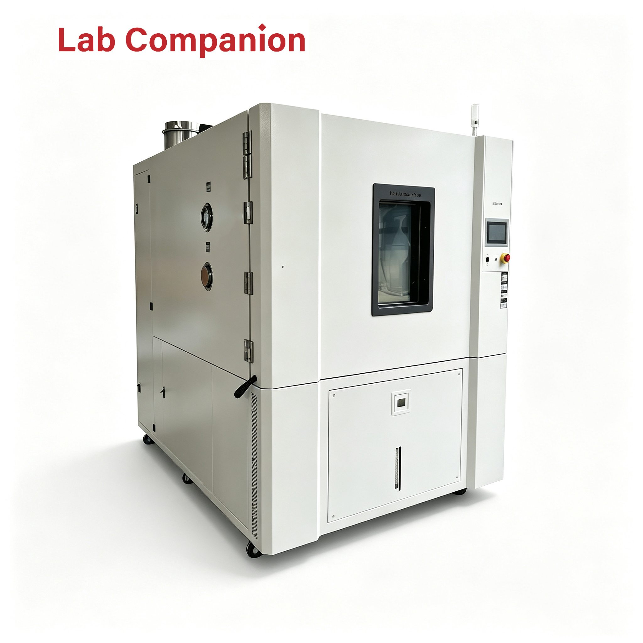
3. Lab Companion Rapid Thermal Cycling Solution for Liquid-Cooled Servers
3.1 Wide Temperature Range and Multiple Ramp Rates
Lab Companion thermal cycling chambers cover -70°C to +150°C, with adjustable ramp rates of 5°C/min, 10°C/min and 15°C/min. Users can select the appropriate profile based on cooling architecture and real operating conditions. This avoids under-testing from insufficient ramp speed and prevents continuous full-load operation that increases energy consumption and shortens equipment service life.
3.2 System-Level Fixtures and Feedthrough Interface
Custom heavy-duty sample racks and restraint structures accommodate rack-style server units. Configurable feedthrough ports support powered testing. Port quantity and positions can be adjusted to reduce airflow disturbance from internal cable bundling. Temperature fluctuation is controlled within ±0.3°C and temperature deviation within ±2°C, ensuring comparable thermal response across different locations on the DUT.
3.3 Automatic Data Logging and Factory Digital Interfaces
Temperature profiles and test data are logged automatically. Thermal response at every cycle can be traced to specific timestamps to correlate performance drift with thermal events. The system supports MES, EAP and SECS-GEM communication interfaces for integration into automated production lines, eliminating manual transcription errors and supporting high-volume reliability validation.
4. Test Execution Recommendations
4.1 Define a Clear Thermal Profile
The profile shall specify temperature limits, dwell time, ramp rate, cycle count and pass/fail criteria, aligned with the product’s actual operating environment. Ambiguous profiles lead to inconsistent test conditions, non-comparable data and poor reusability for future product revisions.
4.2 Define Boundary Conditions for Powered Testing
Set clear boundaries for powered operation: maximum surface temperature of DUT, maximum quantity per load, and handling procedures for unexpected power loss or reset. Verify that the coolant will not solidify or precipitate at low temperatures to avoid blockage during cycling. Embed these rules in SOPs to mitigate risks proactively.
4.3 Collaboration with Reliability Teams
The chamber delivers a stable controlled thermal environment and complete data recording. Definition of thermal profiles and failure judgment remain the responsibility of reliability engineers. Alignment on acceptance criteria before testing and joint data review after testing ensure traceable conclusions. Superior equipment capability cannot replace engineering judgment of the DUT.
Upon test completion, archive temperature profiles, performance logs and unit IDs together. System-level tests generate large datasets. Standardized archiving enables cross-model comparison and failure traceability for future iterations.
Conclusion
Thermal cycling validation for liquid-cooled servers is essentially a systematic verification of the entire system’s thermal compatibility. With a wide temperature range of -70°C ~ +150°C, adjustable ramp rates from 5°C/min to 15°C/min, heavy-duty fixtures for full rack loading, sealed feedthrough ports, automatic data logging and industrial communication integration, Lab Companion provides a proven, ready-to-deploy system-level rapid thermal cycling reliability solution for liquid-cooled AI servers.
Wenn Sie an unseren Produkten interessiert sind und weitere Einzelheiten erfahren möchten, hinterlassen Sie bitte hier eine Nachricht. Wir werden Ihnen so schnell wie möglich antworten.






 Ein Angebot bekommen
 IPv6-Netzwerk unterstützt